Home
Student Biography
Buidling Statistics
Thesis Abstract
Technical Assignments
Thesis Research
Thesis Proposal
Presentation
Final Report
Reflection
Contact Me
eStudio Homepage
   
Note: This web site is best viewed in Mozilla Firefox, 32-bit Internet Explorer, or 64-bit Internet Explorer with Compatability View.

Building Name

  • Integrated Sciences Building

Location

  • Northeast United States

Occupant

  • Not Released for Publication

Building Function

  • Educational & Research Laboratory

Building Size

  • 133,847 Square Feet
  • 5 Stories Above Grade
  • Mechanical Penthouse on 6th Level
  • Partial Basement

Construction Dates

  • Start Date | October 7, 2009
  • Schedule for Substantional Completion | July 1, 2011

Cost Information | *As listed on Owner website

  • Competitve Stipulated Lump Sum | $49,689,001
  • Total Construction Cost Estimate | $52,100,000

Delivery Method

  • Design - Bid - Build

Project Team

Architecture

The Integrated Sciences Building will be a 133,000 square-foot facility built in a northeastern United States city. The facility will support the Department of Bioscience at a major University with 39 laboratories for Biomedical Engineering, Biology and Chemistry, and a Fossil Preparation Laboratory.  It will also incorporate classrooms, faculty offices, a ground floor café, 240-seat auditorium, and a Career Development Center.  The design is by the renowned firm, Diamond + Schmitt Architects, Inc. and is intended to reinvigorate the lively urban campus with excellent modern and sustainable architecture.  Besides being an environmentally responsible building, its most prominent features are the grand 5-story atrium with skylights and natural daylighting, 4-story Bio Wall and a modern spiral staircase.  The exterior appearance of the building is truly unique, featuring a facade made of recycled stone panel cladding with metal accents as well as varied geometries like the elliptical rotunda lounge and the sawtooth atrium skylight window pattern. The many unique features of the buidling combine to create a sophisticated new building with a modern presence.

Applicable Codes

  • Building Code | 2006 International Building Code with Local Amendments
    • Construction Type “1B Protected Noncombustible Construction”
  • Mechanical Code | 2006 International Mechanical Code with Local Amendments
  • Fuel Gas | 2006 International Fuel Gas Code with Philadelphia Amendments
  • Electrical Code | 2006 ICC Electrical Code with Local Amendments
    • ICC Adopts and Amends NFPA 70-2005
  • Fire Code | Local Fire Code Based on 2006 International Fire Code with Local Amendments
  • Fire Protection Codes
    • NFPA 10-2001 | Portable Fire Extinguishers
    • NFPA 13-2002 | Standards of Installation of Sprinkler Systems
    • NFPA 14 - 2000 | Standpipes in Stairwar at Intermediate Floor Level Landing
    • NFPA 72 -2002 | National Fire Alarm Code and Voice/Alarm Communication
    • NFPA 92B - 2005 | Smoke Control System

Zoning Requirements

  • Institutional Development District (IDD)
    • Minimum Lot Area | 3 Acres of Contiguous Property
    • Maximum Gross Floor Area | 400% for All Buildings
    • Maximum Occupied Area | 70% of Lot
    • No Front, Side, or Rear Yards Required
    • Maximum Height | None Required
    • Parking | Located Within 1,000 Feet of Building
      • For IDD Declared Post-03.31.1978 | One (1) Space per 3,000 Square Feet

Historical Requirements

  • No Historical Requirements

Building Enclosure


StoneLite® Aluminum Honeycomb Stone Cladding

Building Facades

The most prominent façade material is a Stone Aluminum Honeycomb Cladding material made by StoneLite®.  The panels consist of a 75% recycled aluminum perforated honeycomb backing which provides rigidity and structure for the stone facing.  The exposed recycled stone is combined with a resin to fill voids.  Together the stone, resin, and aluminum create a durable exterior panel that is made largely of recycled materials. 

In other portions of the façade, Aluminum panels are utilized. Smooth pre-finished aluminum panels are used to contrast the stone cladding and frame the 5th floor curtain wall outcropping on the southwest corner of the building.  The material used is an Alucobond 4mm Aluminum Composite Material (ACM) with Bright Silver finish.

5th Floor SW Corner Outcropping

Alucobond 4mm ACM

Horizontal profiled aluminum cladding is used as an enclosure for the rooftop penthouse, the elevator shaft on the northeast side of the building, and the saw-tooth window section above the atrium. The material is Kalzip Exterior Cladding Panels.

SE Rooftop Saw-Tooth Feature

Kalzip Aluminum Cladding Panels

Surrounding the elliptical rotunda that extends from ground level to the 6th floor are custom fabricated aluminum sunshades.  The width of the shading devices are 20” and are mounted on brackets so that the outer edge is 24” from the exterior glass.

Rotunda Sun Shade Detail

Southern Rotunda Student Lounge Feature

Unitized Window Details

Window Glazing


Motor-Actuated Window Elevation

The glazing assembly is 1” thick, consisting of two 1/4” thick glass panes separated by a 1/2” argon-filled space.  The glass has a transmittance of 61% for visible light and only 19% for solar heat.  The shading coefficient is 0.37.  The exterior windows on the stone cladding portion of the façade are unitized at three different widths, but have consistent floor-to-ceiling height with spandrel glass on the top and bottom portions.  The details of the windows are shown below in the three different widths: 2’-0”, 3’-8”, and 5’-8”.  The details also include annotation for Operable Casement Windows that are used on the southeast facades.

Curtain walls are used on a large portion of the ground level as well as on the outcropping on the southwest side of the 5th floor.  On the ground level curtain walls, doors are integrated as required into the mullion pattern, which are spaced predominantly at 3'-0" horizontally and extend from floor to ceiling.

Near the west stairwell and the east entrance, a different façade layout is dictated by the window arrangements.  These windows are motor actuated, operable awning windows which are mechanically opened and closed.  They are designed to release smoke from the building in case of fire.  To the right is a portion of the elevation of the east entrance with this window arrangement highlighted.

Roofing

The roofing material is a White Carlisle Sure-Weld FB115 Thermoplastic-polyolefin (TPO) Roofing membrane. The assembly includes 4” of rigid roofing insulation over concrete or steel structure, depending on its location.  The insulation provides an R-Value of 28.6.

Sustainability Features

The Integrated Sciences Building was initially intended to be the University's first LEED Silver building but the effort has been upgraded and the new target is LEED Gold status on the v2.2 scale.  There are 43 LEED points targeted including water use reduction, optimized energy performance, use of regional and recycled materials, construction waste management and enhanced Indoor Environmental Quality, among others. 

One of the goals of the building was to set a new standard for architectural and sustainable design that will spark students and faculty to engage in an interactive learning environment.  Front and center in this effort is the fact that the Integrated Sciences Building is going to be the first United States University building with a living, breathing Bio Wall.  The Bio Wall is a 5-story living wall with live plant species that offers improved energy efficiency and indoor air quality.  The wall is expected to cool the large atrium during summer months and act as a humidifier during the winter.  It will also remove carbon dioxide from the indoor atmosphere and filter Volatile Organic Compounds.  The Bio Wall is a visual representation of all of the sustainable features of the building, from the enhanced mechanical system, of which it aids by enhancing air quality, to the renewable materials and growth of technology that was used in the building.


Building Statistics - Part II

Construction

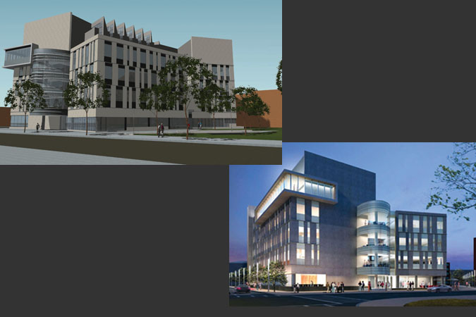
Construction of the University Sciences Building began October 7, 2009 and is scheduled for Substantial completion on approximately July 1, 2011.  Turner Construction Company is the construction manager at risk.  The delivery method is Design-Bid-Build with a competitive bid, Stipulated Lump Sum contract valued at $49,689,001 according to the owner’s website.  The overall estimated cost of construction is approximately $52.1 million.  The project is being designed and constructed under enhanced commissioning requirements to meet LEED specifications. 

Electrical

Incoming power is provided from the campus 13.2kV service via 3-#4/0 wires to the switchgear in basement electrical room of the University Sciences Building.  This service feeds a main transformer, located in the 5th floor electrical room, which provides the 5000-amp, 277/480V 3-phase main panel and supports critical mechanical loads, emergency panels, and substation loads.  There is a 150kVa 120/208V transformer that serves receptacle panels.  Upon utility power failure, there are two automatic transfer switches (ATS-1 and ATS-2) which will send a start signal to the Emergency Diesel Generator to maintain power to the Emergency Panel and Main Standby Panel for Life Safety Systems and Emergency Lighting Systems.  There is also a Fire Pump Transfer switch to provide power to the fire pumps in case of emergency.  The Diesel Generator is 600kW, 480V, 3-phase with a 0.8 power factor and 750kVA.

Lighting

The lighting system includes a variety of different fixture types and sizes.  The layouts generally include T8 Linear Fluorescent fixtures which are surface mounted, recessed into the ceiling, or direct/indirect pendant mounts.  The lamps are predominantly 4 foot long units arranged end-to-end in strips.  This holds constant in classrooms, auditoriums, teaching labs, offices, and student lounges.  The linear fluorescent fixtures are accented by compact fluorescent downlights and a variety of other lamp styles.  There are interior LED accents as well as outdoor LED and Metal Halide fixtures.   

Interior lighting control is performed by wall-mounted switches, occupancy sensors, timer switches, and dimmable lighting control systems.  Occupancy sensors are installed in restrooms, offices, public corridors and other public areas.  This prevents use of fixtures without occupancy, and energy savings as a result.  Timed switches are used for the same purpose in irregularly occupied spaces such as mechanical electrical rooms.  Dimmable lighting ballasts are installed in the large rooms including the 240-seat auditorium, conference and seminar room and large classrooms.  During power failure, designated emergency fixtures and exit signs remain illuminated for egress purposes.

Mechanical

The HVAC system that serves the University Sciences building is a Variable-Air-Volume (VAV) system consisting of nine Air Handler Units (AHUs).The air handlers use Chilled Water coils and Glycol Heating coils as well as MERV-8 rated filters.  The VAV system uses terminal reheat as necessary as well as Supply Air Modulation.  Supply air flow rates are based on ASHRAE Standard 62.1.  The Laboratory spaces will be supplied with 100% Outdoor Air for Indoor Air Quality.  Heat Recovery Loops will be used to increase the overall building efficiency by an estimated 29%, which is well above the required 14% for LEED certification.

The Chilled water system consists of a Primary/Secondary chilled water system with two 620-ton Electric Centrifugal Chillers consuming 375kW each at full capacity.  The chillers will use the refrigerant HFC-134a.  The condensing system includes two 620-ton Induced Draft Single Cell Cooling Towers each powered by 40 horsepower motors.

Heating coils are supplied by the campus steam system.  Steam is supplied to the system at 200psi and goes through two pressure reducing valves from 200psi to 60psi and then 60psi to 12psi.  Steam is used to heat a 30% glycol mixture for the heating coils and some steam is used for humidification in the air handling units.  Supplementary heating needs throughout the building are met by Electric Unit Heaters and hot water radiant panels. 

For domestic water use, there are two 250-gallon hot water tanks in the basement mechanical room which are heated by the steam distribution system.  A 30-gallon electric water heater provides supplemental heating to maintain a non-potable hot water loop temperature.  There is a Reverse Osmosis multiple purification water tank on the penthouse level.  For service to the laboratories, there is piping throughout the building for Carbon Dioxide, Nitrogen and Natural gases.

Structural

The structural design of the Integrated Sciences Building is complex due to the unique shapes that make up the plan of the building.  Most of the structure is reinforced concrete columns and floors.  The underground structure of the building is made of 83 Caissons that range is diameter from 36 to 60 inches.  Each caisson cap is 40 inches in depth and square with the same width as the diameter of its corresponding caisson.  The columns in the building are a mixture of round and rectangular columns.  The round columns are 24 inches in diameter and are built with a special, plastic-lined form to produce a smooth finish in any location that they are exposed to view by the occupants. The rectangular columns are either 36”x30” or 34”x16” and are hidden in walls away from the occupant’s vision.  The floor system is comprised of a Filigree slab floor and beam system.  This system consists of 2-1/4” thick manufactured concrete slabs shipped to field to be assembled, shored, and poured.  Slabs include polystyrene foam blocks to reduce floor mass.  This method is used in place of traditional cast-in-place construction to speed up the building schedule by reducing the time required for formwork placement.  The concrete beams are integrated into the floor system.  They range in depth from 10 to 24 inches and width from 23 to 60 inches.  Flexural reinforcement in varying sizes is embedded in the beams according to ACI code.

Transfer beams are used to support the walkways that surround the cantilevered walkways around the atrium on each floor.  The building has Shear Walls at both the West and South Stairwells as well as around the Elevator Shaft.  The elevator shaft includes a unique 30⁰ angle between two walls and another exterior wall connecting them.  There is also a set of perpendicular shear walls in the SE portion of the building and another single North to South Shear wall in the East portion.  All of the shear walls extend from at or below the basement floor level to at least the finished roof level.  Some extend beyond the finish roof because of the stairwell access and elevator equipment rooms at rise to higher points.

The structure at the top of building makes a transition from reinforced concrete to structural steel.  On the southeast portion  and part of the northeast portion of the building, this transition is just above the 5th floor.  On the eastern and northwestern portions of the building, the transition from concrete to steel structure is at the mechanical penthouse level floor.  The column sizes for the structural steel framing are either W8x48 or W8x40 depending upon local loads.  Cross bracing on selected exterior bays provide lateral bracing.

The 240-seat auditorium located in the northeast corner of the building on the ground floor and extending down to basement level has a structural steel frame that creates the sloped, allowing for a tiered stadium seating arrangement.  This frame includes W24x103 girders with W10x26 and W12x26 joists.

The roof structure is one of two assembly types.  Over some areas it is rigid foam over a concrete slab with White Carlisle Sure-Weld FB115 Thermoplastic-polyolefin (TPO) membrane.  Over the mechanical penthouse on the north and east portions of the building, where there is a steel roof structure, the roof is the same rigid foam insulation and TPO membrane over exterior grade sheathing.


Senior Thesis Main PagePenn State UniversityPenn State Architectural EngineeringAE Compter Labs


About CPEP:
The Capstone Project Electronic Portfolio (CPEP) is a web-based project and information center. It contains material produced for a year-long Senior Thesis class. Its purpose, in addition to providing central storage of individual assignments, is to foster communication and collaboration between student, faculty consultant, course instructors, and industry consultants. This website is dedicated to the research and analysis conducted via guidelines provided by the Department of Architectural Engineering. For an explanation of this capstone design course and its requirements click here [+].


This page was last updated 08.31.2010 by Christopher Putman and is hosted by the Pennsylvania State University Architectural Engineering Department. © 2010 All Rights Reserved.

Note: While great efforts have been taken to provide accurate and complete information on the pages of CPEP, please be aware that the information contained herewith is considered a work-in-progress for this thesis project. Modifications and changes related to the original building designs and construction methodologies for this senior thesis project are solely the interpretation of Christopher Putman. Changes and discrepancies in no way imply that the original design contained errors or was flawed. Differing code references, assumptions, requirements, & methodologies have been incorporated into this thesis project; therefore, investigation results may vary from the original design.