|
Note: While great efforts have been taken to provide accurate and complete information on the pages of CPEP, please be aware that the information contained herewith is considered a work-in-progress for this thesis project. Modifications and changes related to the original building designs and construction methodologies for this senior thesis project are solely the interpretation of Ashley Bradford. Changes and discrepancies in no way imply that the original design contained errors or was flawed. Differing assumptions, code references, requirements, and methodologies have been incorporated into this thesis project; therefore, investigation results may vary from the original design.
|
|
| b u i l d i n g . s t a t i s t i c s |
|
| |
| |
|
|
| |
|
g e n e r a l . b u i l d i n g . d a t a |
|
p r o j e c t . t e a m |
| ∙ building name: |
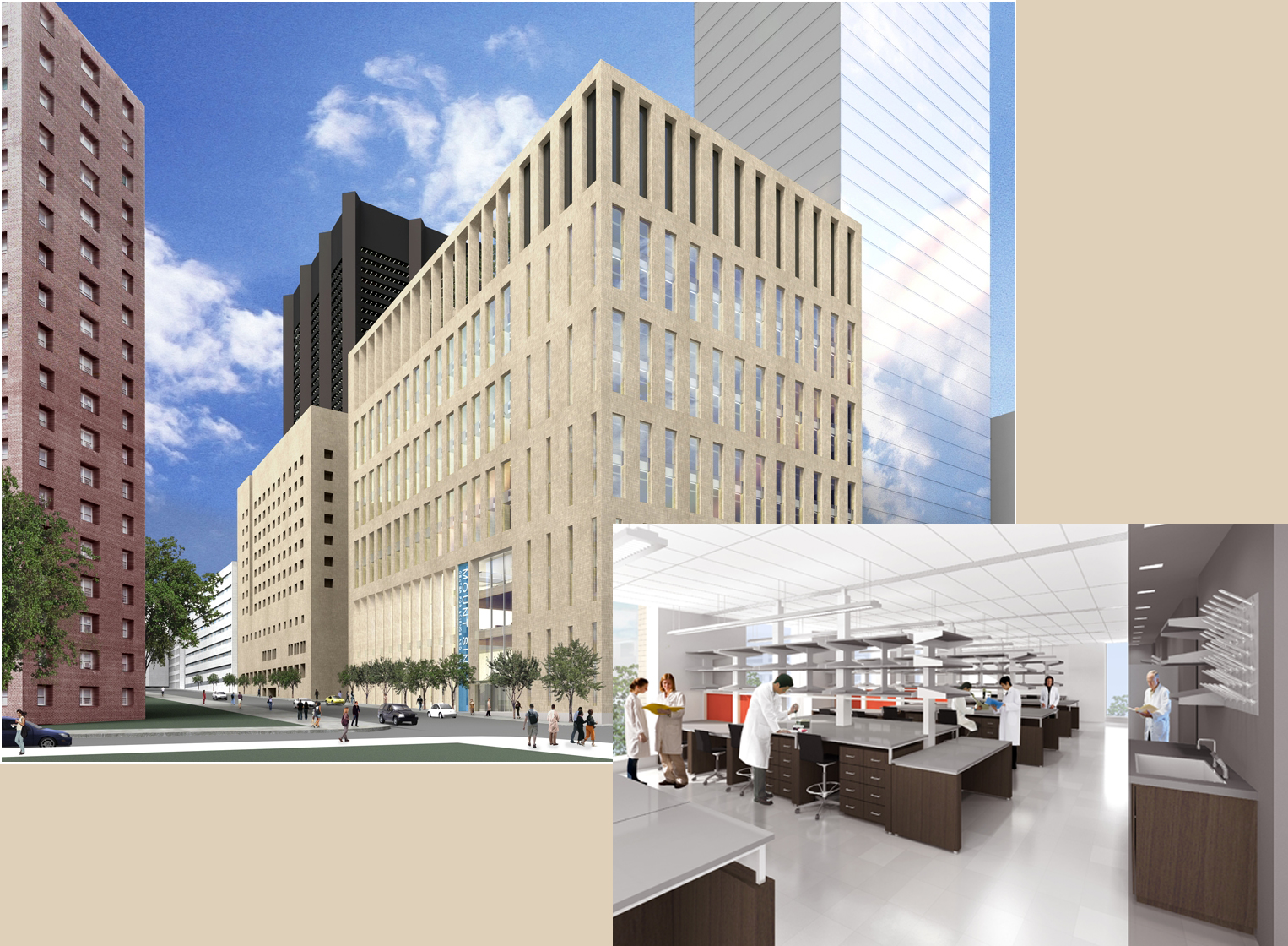
Center for Science and Medicine |
|
∙ owner: |
(confidential) |
| ∙ building site: |
Manhattan’s Upper East Side |
|
∙ architect/structural engr: |
Skidmore, Owings, and Merrill, LL |
| ∙ building occupant: |
(confidential) |
|
∙ lab planning consultant: |
GPR Planners Collaborative, Inc. |
| ∙ building function: |
biomedical research & clinical trials |
|
∙ MEP engineer: |
Jaros Baum & Bolles |
| ∙ size: |
443,291 square feet |
|
∙ civil engineer: |
Langan Engineering |
| ∙ height: |
184’-0” |
|
∙ lighting consultant: |
SBLD Studio |
| ∙ number of stories: |
11 above grade, 2 below grade |
|
∙ landscape consultant: |
Quennell Rothschild & Partners, LLP |
| ∙ dates of construction: |
April 2008 – July 2011 |
|
∙ security consultant: |
Kroll |
| ∙ project cost: |
approximately $235 million |
|
∙ construction manager: |
Bovis Lend Lease |
| ∙ project delivery method: |
design-bid-build |
|
|
|
| |
|
|
|
|
| |
|
|
|
|
| |
|
|
|
|
a r c h i t e c t u r e |
|
|
|
| |
|
|
|
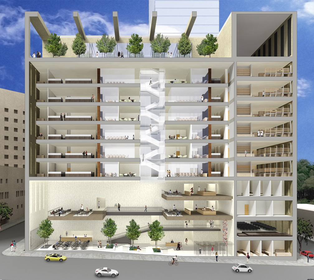
∙ design and functional components:
The research lab is designed for a dual mission: “Investigation and Discovery” as well as “Treatment and Healing.” The building is organized and shaped by this thematic double program. On the north and south edges of the site, two linear lab bars encompass a core of support spaces. The building’s east edge has been designed as an almost seamless extension of the busy street below, and rises from the public realm as an engaging 4-story Atrium. Situated within the building are 6 additional floors of wet lab research space, 1½ floors of clinical space, a clinical trial area, and space for research imaging. A 40-story residential tower will also rise on the site adjacent to the lab, but the buildings are clearly defined as two separate entities. |
|
| |
∙ applicable codes:
IBC 2003
NFPA 99 – Health Care Facilities
NFPA 101, 1997 – Life Safety Code
Building Code of the City of New York
New York State Energy Conservation Code 1979
ASME A17.1 National Elevator and Escalator Safety Code 2000 |
| ∙ zoning: (still researching) |
|
|
| |
|
|
| |
|
∙ building envelope:
Because of the project’s intent to achieve LEED certification, exterior enclosure has been designed to conserve energy and use products friendly to the environment. The building’s Main Entrance and Atrium Lobby will be profiled with bronze-clad stick-built framing glazed with low e-coated laminated glass. The remainder of the building will be clad in brick-faced precast concrete panels and architectural metal panels. Punch window glazing will consist of painted aluminum-framed windows with a typical 2-story height.
Roofing will be insulated membrane assemblies over the majority of the building. A garden roof assembly, including moisture retention mats, water drainage/storage mats, and root barriers, will be applied at the garden terrace level. |
| |
| |
|
|
| |
|
|
p r i m a r y . e n g i n e e r i n g. s y s t e m s |
| |
|
|
The careful and innovative design of each primary engineering system has been intended to contribute to the project’s overall goal of achieving LEED Gold.
construction
The construction of CSM is slated to begin in April 2008 and is scheduled for completion by July 2011. The general contractor is Bovis Lend Lease, and the project will be delivered by a design-bid-build method. The use of building information modeling (BIM) in the design and planning of CSM is expected to reduce overall project schedule and cost while also making on-going coordination more efficient and seamless. No other details can be provided at this time due to the project’s early phase of design. |
| |
|
|
electrical
Power to CSM will be supplied by a 277/480 V, 3 phase, 4 wire system distributed by three 5kV feeders. The system will step down to 120/208 V for receptacles and incandescent lighting. Laboratory floors will be served by an enclosed plug-in busway system, with a minimum of 3 takeoff positions per floor, run vertically through the building.
A generator plant utilizing two 1,200 kW diesel engine-generator sets will be provided on-site. Each generator will be a diesel engine driven unit with automatic starting capability (10 seconds maximum) and fuel storage for a minimum of 24 hours at rated load. |
| |
|
|
lighting
Lighting fixtures are to be fluorescent, high intensity discharge lamps (277V) and incandescent lamps (120V). Automatic lighting control will be provided to all areas of CSM and will be controlled from a central system. Each perimeter office or laboratory will be powered by a photosensor-dimmable lighting control system with capability of local override and occupancy sensor. Interior open areas will be controlled through a programmable lighting relay system.
|
| |
|
|
mechanical
Laboratory, vivarium, and imaging spaces will be served by a total of eleven “once through” supply and exhaust systems using 100% outdoor air. All labs will have individual direct digital temperature and pressurization control. Conference and amenity spaces will be served by two independent supply and return systems.
The lobby/atrium will be provided with its own independent supply and return system. The main level of the atrium will receive air using a displacement supply air arrangement, while the balcony waiting areas of the atrium will be conditioned by a combination of perimeter fan coil units and a radiant floor heating/cooling system.
Much of CSM’s complex mechanical equipment will be located on the lower levels of the adjacent residential tower (below 160 ft). This tactic makes use of the space in the future tower which may be less desirable (any view from the tower below 160’ would be blocked by surrounding buildings) and also minimizes the need for additional height or excavation of CSM.
|
| |
|
|
structural
The Center for Science & Medicine employs a steel frame structural system with composite metal deck on each floor. Typical floor heights are 15’-0” above grade and 24’-0” below grade, with column bays of 21’-0” x 21’-0” within the building core and 21’-0” x 43’-0” elsewhere. The foundation consists of reinforced concrete spread footings ranging from 4’x4’x2’ to 8’x8’x4’ (l x w x h) in size at a maximum depth of 49’-0” below grade. Seven of the total forty-three footings will be designed to support columns from both the research center and the residential tower, as dictated by their location at the CSM / tower interface. Typical gravity columns are nominal W14 sections, and columns acting as part of the lateral system range from nominal W24-W36 sections.
Lateral resistance to wind and seismic loads is provided by a combination of braced and moment resisting steel frames. In the North/South direction, lateral loads are resisted by a system of diagonally-braced frames around the service core area of the building’s interior. In the East/West direction, lateral loads are taken by a dual system of perimeter beam/column moment frames and the diagonally-braced frame around the service core. The moment frames first occur on the third level and then alternate levels up through the building’s roof (a total of five floors with moment frames).
The flat roof system is a concrete slab on composite metal deck. Supporting this deck are wide flange steel beams ranging from W12- W36 sections and spaced approximately 10’-6” on center. A portion of the roof has been designated as a green roof, but design has not progressed enough to gather significant detail at this time.
It is also worth noting that the structure was designed to meet stringent vibration criteria, 2000 micro-inches per second, in selected areas. |
| |
|
|
| |
|
|
e n g i n e e r i n g . s u p p o r t. s y s t e m s |
| |
|
|
fire protection
CSM will have two fire services from water mains already existing in adjacent streets. The interior of the building will employ an Ordinary Hazard sprinkler system, which provides 0.16 gpm over 1800 sq. ft. Pre-action sprinkler systems will be installed for specialized imaging equipment and IT server rooms. Fireproofing of structural members will be in accordance with NYC Building Code. All major columns, girders, and trusses will have a 3hr fire rating. Floor slabs, beams, and other members supporting only one floor will have a 2 hr fire rating. |
| |
|
|
| transportation |
|
|
Elevators:
A core of 4 elevators located in the center of the main lobby serves the building’s research population. Two of these elevators will be sized as standard 3,500 lb capacity, while the other two will be oversized at 4,500 lb capacity. The oversized elevators will allow for the potential transport of a heavy stretcher carrying a clinical patient. These four core elevators will travel from the lower basement level SC2 up through Level 11. Two additional elevators will be designated for clinical use, as well as providing service to the conference areas. These elevators are also located off of the main lobby, adjacent to the building core, and they will be sized as standard 3,500 lb capacity. They will travel from Level 1 to Level 4. Two service elevators will be located in service corridor of the building core and will be capable of handling 6,000 lb. The service elevators will travel from Level 1 to Level 11. All elevators will be provided with a card reader and security cameras. An elevator management computer station will be located at the front desk to enable security personnel to monitor the status of the elevator system.
Stairs
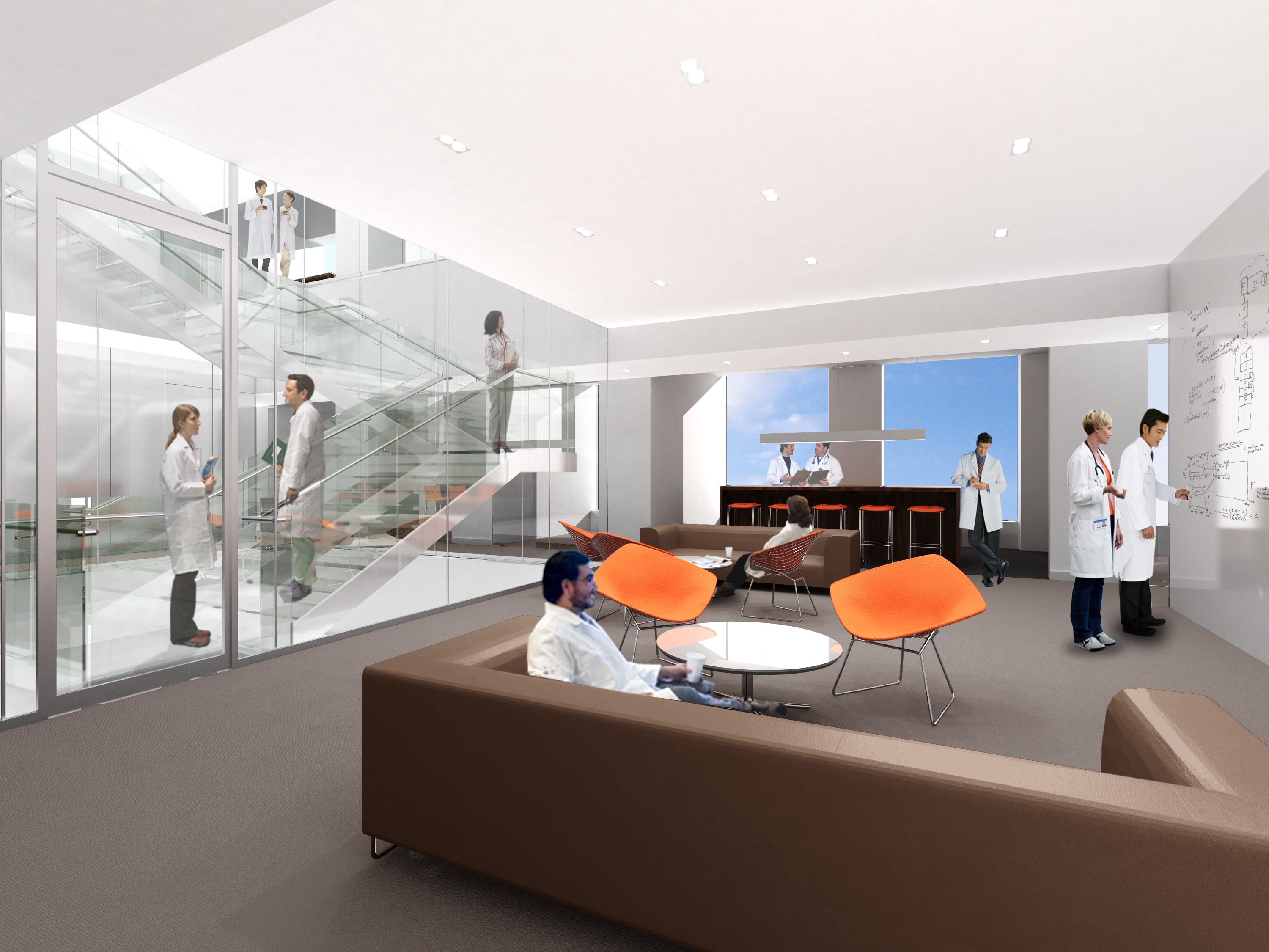
The main stairwell is located inside of the building core and runs from the lower basement level SC2 up through Level 11. It can be accessed from the main lobby. Also in the atrium is an open stair linking the first floor lobby to the second floor balcony area. Another main stairwell is inside of the core, but begins at Level 2 and runs up to the roof.
Smaller, less accessible stairwells are located throughout the building as well. In the Northwest corner, a stair runs from Level SC2 through Level 11. In the Southwest corner, a stair runs from Level SC2 through Level 2. Linking typical laboratory Levels 5 through 11 is a square-shaped stairwell, its open center looking down into the lobby below and its roof covered with glass.
|
| |
telecommunications
Telephone service will be provided to the building. The system will consist of empty conduit, raceway, and/or trough from incoming service area to outlet boxes. Four 4-inch conduits will be run from the mainframe room to each of two telecommunications closets. Closets on laboratory levels will be stacked. |
| |
special systems
An extensive security system has been designed to keep the Center for Science & Medicine highly protected at all times, from the inside and out. It will be employed as follows:
An alarm monitoring and access control (ACAM) system will provide centralized monitoring and controls within the building. This will be achieved by a building perimeter alarm system, electronic access control in elevators and other specialized areas, and alarm monitoring in designated interior spaces. An intercom system will be employed to allow two-way communication between security posts and vehicular entrances, and duress buttons will be located throughout the building for use by personnel in the event of a medical or security emergency. Closed circuit television cameras (CCTV) will be placed at perimeter entries, labs and vivariums, the loading dock, the pedestrian tunnel, fire exits, elevators, and in the main lobby. A computerized visitor management system will be put in place to facilitate visitor/patient access to the building, and a computerized delivery management system will be used to control loading dock access. Both systems will be capable of archiving information on visitor/patient arrival and on the receiving of deliveries for future needs.
|
| |
| |
|
|
|