Residence Inn
By Marriott
Alexandria, VA
Julia E. Phillips
Construction Management
| Student Biography |
| Building Statistics |
| Thesis Abstract |
| Technical Assignments |
| Thesis Research |
| Thesis Proposal |
| Presentation |
| Final Report |
| Reflection |
Senior Thesis e-Studio |
| User Note: “Note: While great efforts have been taken to provide accurate and complete information on the pages of CPEP, please be aware that the information contained herewith is considered a work‐in‐progress for this thesis project. Modifications and changes related to the original building designs and construction methodologies for this senior thesis project are solely the interpretation of Julia Phillips. Changes and discrepancies in no way imply that the original design contained errors or was flawed. Differing assumptions, code references, requirements, and methodologies have been incorporated into this thesis project; therefore, investigation results may vary from the original design.” |
Building Statistics
General Building Information:
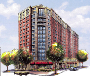
Building Name: Residence Inn by Marriott
Location and Site: 2345 Mill Rd., Alexandria, VA 22314
Building Occupant: Marriott Hotels
Occupancy / Function Type: 181 room Hotel
Size: 169,206 sf with underground parking
125,548 sf residential hotel rooms
Total Levels: 15 stories above grade, with 3 below grade of underground parking
Project Cost: $33.5 Million
Primary Project Team:
| Owner: | Miller Global Properties 4643 South Ulster Street, Suite 1500 Denver, CO 80237 www.millerglobal.com |
| Construction Manager: | Balfour Beatty Construction 3924 Pender Drive Fairfax, VA 22030 www.balfourbeattyus.com |
| Architect: | Davis Carter Scott 1676 International Drive, Suite 500 McLean, VA 22102 www.dcsdesign.com |
| Civil Engineer: | Christopher Consultants 9900 Main Street, Fourth Floor Fairfax, VA 22301 www.christopherconsultants.com |
| Electrical Engineer: | Dynalectric Company 22930 Shaw Road., Suite 100 Dulles, VA 20166 www.dynalectric.com |
| Electrical Consultant: | Girard Engineering 1355 Beverly Road, Suite 240 McLean, VA 22101 www.girard.com |
| Mechanical / Plumbing Engineer: | Southland Industries 22340 Dresden Street, Suite 700 Dulles, VA 20166 www.southlandind.com |
| Structural Engineer: | Smislova, Kehnemui and Associates, PA 6101 Executive Boulevard, Suite 250 Rockville, MD 20852 www.skaengineers.com |
Dates of Construction: |
Start: | November 2006 |
| Finish: | September 2008 |
Project Delivery Method: Design – Bid – Build for CM @ Risk AIA Document A121, Structure, Civil, Electrical
Design – Build for Mechanical and Plumbing (Southland)
Codes: |
2003 Virginia Uniform Statewide Building Code (USBC) |
Zoning: |
CDD-2 Coordinated Development District, Special Use Permit Hotel |
Historical Requirements:
In Alexandria, Virginia, every new building that is designed and built must go through a rigorous approval process. The city must approve the building use, design, façade, exterior penetrations, colors, and each building must have at least 20 LEED points. After this approval takes place the façade cannot change without re-doing the same process to evaluate the changes. The building must have minimum exterior penetrations, and they must be visually appealing or disguised in some way to hide them from the public view. The exterior colors also must consist of the very top of the building being a light beige color, with a pink / mauve brick façade in the middle, and a red brick on the base. As well as each portion of the building being distinct and identifiable as a top, middle, and bottom. The city also requires an appealing exterior walk with shade trees and wide walkways to blend each new building with the existing buildings.
Structural System:
The mat slab foundation, the three underground parking levels, and the post tensioned floor decks are made of cast in place concrete. The mat slab thickness ranges from 30, 36, to 48 inches thick is 5000psi normal weight reinforced concrete and has a minimum 4” working slab of 2000psi concrete underneath it to aid in stopping water penetration. The drainage and sump pump pits were formed in the ground during pouring. The walls and columns of the parking levels are minimum 18’ spans with average 10’ by 10’ drop panels and formed with vertical reusable formwork with 5000 psi normal weight concrete. The parking level floors are 8” thick and made of 5000 psi cast in place normal weight concrete. The typical post tensioned floors above grade are 5000psi normal weight concrete, once the strength reaches 3000 psi tensioning of the cables can occur. All exterior and exposed cast in place concrete is air entrained 3000psi concrete.
The façade of the building above grade is comprised of pre-cast concrete with a rigid insulation and CMU backup system. The pre-cast concrete is prefabricated in panels to look like red brick to help it blend with the other buildings in Alexandria. The precast panels will be connected vertically with tee connections, and horizontally with ties imbedded in the mortar joints of the CMU block backup system.
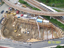
Support of Excavation:
The excavation needed support on all sides and is clear of all permanent construction work. However, due to the restrictions working around the metro tracks tie-backs were not allowed in fear of disrupting or moving the column foundations that support the metro, instead large rakers had to be installed across the site. On the other three sides that did not border the metro a regular tie-back and lagging system was used. There were some issues during excavation with failing tie-backs; in those areas rakers were installed to support the walls. Also one raker had to be moved since it was placed on a future column line. This was done because the sheeting and shoring is to remain in place during construction.
Mechanical System:
The system is primarily a chilled fan coil unit system with electric heating coils in the fan coil units for heat. There is one air cooled chiller located on the roof that has a nominal capacity of 155 tons which pumps chilled water to the coils inside the fan coil units in each guest room. The variable air volume air handling unit located on the second floor that provides air for the lobby, offices and all other spaces on the second floor. The variable air volume boxes in the ceiling also have electric heat coils to provide heat to the spaces. There are two natural gas fired boilers that have a capacity of 1,800,000 btu input and 1,530,000 btu output. The boilers are used for domestic hot water needs and for heat inside the second floor air handling unit needs. The system also has two shell and tube heat exchanges used to generate the domestic hot water which have a capacity of 1,424,000 btu each.
Fire Protection:
The fire protection system in the building is rather complex and some aspects are added as a “code plus” to make the system more advanced. The roof top makeup air unit provides ventilation for the corridors, bathroom exhaust, and smoke ventilation. The unit normally operates at a low flow but increases once smoke has been detected by a smoke detector located in every room in the building. The smoke exhaust system is designed to provide about 12 air changes per hour, 67% of the volume on the fire floor, and pressurize the stairwells and hoistways. This is done to control the migration of smoke throughout the building, mainly focusing on the means of egress into and out of the building. While the system is in fire mode, no service will be provided through the small VAV boxes. When the smoke detectors are tripped fire dampers will open fully enabling the pressurization of the stairwells and hoistways, which means they will remain operable during a fire emergency.
Electrical / Lighting / Telecommunications Systems:
The switchboard is rated at 3000 amps with 480/277 volts, 3 phase, 4 wire system. A typical guest room with all equipment on draws 58 amps. Most lighting fixtures are fluorescent to add efficiency to the design and to attain the appropriate LEED points. The following transformers service the building: one 750 kva feeds the bus-duct riser, which provides 120/208 volts power to all of the guest room panels; seven other transformers provide step down voltage from 480 volts to 120/208 volt power for various areas such as the back of house outlets, low voltage kitchen equipment, corridor lighting and power, and miscellaneous garage power. The backup generator is sized at 400 kw and 480 volt would provide power to all emergency lighting, fire alarm, stair pressure fans, smoke removal fans, fire pump, emergency for elevators, selected circuits for security if the power should ever go out. The telecom load is very small and is accommodated by miscellaneous 20 amp circuits in the telecom closets to run the servers and routers. In the workout room there are 20 amp circuits for each major piece of equipment, like treadmills and plasma screen televisions.
Masonry & Curtain Wall:
There is very little masonry throughout the building; it is only in the CMU back-up wall system and on the face brick façade. The CMU is located behind the per-cast concrete panels with a full bond mortar joint and is designed to help sound attenuation and thermal insulation with the rigid insulation. There is also masonry in the brick paving on the sidewalks, but this is only for aesthetic appeal. The curtain wall system spans the total height on the southeast corner of the building over the lobby entrance is designed to add aesthetic appeal while mimicking the glass curtain wall of the building across the street to create a “column of light” effect on either side of the street when the afternoon sun hits both buildings. The curtain wall is also designed to hide the fact that there is no atrium; the lobby is only one floor in height.
Acoustics:
Shen, Milsom & Wilke performed an extensive acoustical noise study on site before construction began. This was done to learn as much as possible about the sound levels of the metro Yellow Line that runs very frequently at night, about every 5 to 10 minutes. A 24-hour measurement was conducted from 26-27 July 2005. Site measurements were also conducted on 26, 27 & 29 July 2005. Measurements were taken at the grade level and at the elevation of the raised Metro track. Metro trains traveling on the elevated track reached levels of 100 and 102 dBA. Metro trains in service traveling on the grade level tracks reached levels between 85 and 99 dBA depending on whether the operator used the horn when entering or exiting the tunnel. This research in very important to Miller Global because the main focus for every building is the guest experience. Since the World Health Organization (WHO) requires a 30 dBA level sound for good sleep the metro noise could be a large potential problem since most of the metro activity occurs at night.
Once field measurements were taken SM&W performed tests with mock up window assemblies of different STC / OITC ratings that are acceptable to the WHO. Five assemblies were tested all of which outperformed the national regulations. The third assembly proved to be the most cost effective (approximately $200 / SF) which is:
1 ¼" IGU consisting of ¼" Annealed
+ ¾" Air Space
+ ¼" Annealed with
5 3/8” air space and
3/8” laminated
This equals a total frame depth of 9”. The configuration provides an increase in performance of 3 dB at 630 Hz and 6 dB at 4000 Hz, the most critical frequency bands.
Based on this research they concluded that the appropriate window required a Sound Transmission Class (STC) of 59 and Outdoor-Indoor Transmission Class (OITC) of 46. This assembly out performs the WHO and Department of Housing and Urban Development (HUB) requirements of STC 56 and OITC 43 even without the sound barrier that will be installed. Heavy drapes will also be hung on the interior side of the windows to further help sound attenuation and increase the guest experience.
Transportation:
There are three elevators located in one elevator bank in the southwest corner of the building. These elevators run from the lowest P-1 parking level to the highest space on the 15th floor. There are three stairwells labeled A, B, and C. Stair A is located adjacent to the elevator bank in the southwest corner and also runs from P-1 parking to the 15th floor. Stair B is located opposite Stair A in the northeast corner, and only services the underground parking levels to street level. Stair C is located adjacent to Stair B in the northeast corner, and services the first through the 15th floor.
This Page was last updated on October 15, 2007 , By Julia Phillips and is hosted by the AE Department ©2007