User Note:
Note: While great efforts have been taken to provide accurate and complete information on the pages of CPEP, please be aware that the information contained herewith is considered a work-in-progress for this thesis project. Modifications and changes related to the original building designs and construction methodologies for this senior thesis project are solely the interpretation of Monjia Belizaire. Changes and discrepancies in no way imply that the original design contained errors or was flawed. Differing assumptions, code references, requirements, and methodologies have been incorporated into this thesis project; therefore, investigation results may vary from the original design.
|
|
|
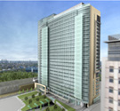
Welcome to Monjia Belizaire's AE Senior Thesis e-Portfolio!
General Building Data
Building Name: City Hospital- Phase I
Location and site: Southeast Pennsylvania
Building Occupant Name: City Hospital
Function types: Research Facility and Central Utility Plant (C.U.P.)
Size:
Phase I: 200,000 s.f.
Phase II: 325,000 s.f.
Number of stories below grade: 3.5 levels
Total number of levels: 11.5 levels
Primary project team:
Dates of construction:
Phase I: March 2005- December 2007 (Estimated)
Building Cost:
Phase I: $156 Million
Phase II: $244 Million
Project delivery method: Construction Manangement at Risk
Architecture
Design and Functional Components:
Phase I is an "L" shaped four-story composite building structure that will provide a research facility, administration space, conference space, and a Central Utility Plant (C.U.P.). Phase II is an 8-floor steel frame building above grade that will be used for research in medicine. City Hospital is seeking LEED Silver Certification for New Construction and is being planned for expansion to as many as 22 stories to accommodate future growth. Once complete, the site will accommodate underground parking, day surgery, imaging, an ambulatory building with outpatient care, and improved facilities for patients, families and employees.
Major national model codes:
NFPA 101 – Life Safety Code
ICC/ANSI A117.1
IBC – International Building Code (2003 EDITION)
NEC – National Electric Code (2002 EDITION)
IPC - ICC International Plumbing Code (2003 EDITION)
IMC - ICC International Mechanical
(2003 EDITION)
Zoning:
C5 - Highest Density Commercial
Historical requirements of building:
Not applicable to this project
Building envelope:
Phase I consist primarily of a concrete masonry unit (CMU) cavity wall system. This system is constructed with a 4” CMU veneer , 2” air space, 2” rigid insulation, a fluid applied vapor permeable air barrier system, and 8” CMU. The only exception to this building envelope system is the concrete shear wall used on east C.U.P. The concrete shear wall is made of a fluid applied vapor barrier on a pour in place concrete wall with 2" semi-rigid insulation pinned to the interior face. The entire envelope is coated with an exterior wall membrane finish.
The roof of the research facility consists of a EPDM roof membrane applied on a pour in place concrete on steel deck. The roof of C.U.P. is constructed by a 4” concrete traffic topping over a structural concrete slab with a 2” rigid insulation system to accommodate traffic on the loading dock.
Building Systems
Construction:
City Hospital holds a lump sum contract with Ballinger Architects to design the structure and the building systems. The project construction is being coordinated by Turner Construction Company and constructed by its prime contractors. Turner acts as a construction manager at risk and holds lump sum contracts with its prime contractors. City Hospital holds a guaranteed maximum price contract with Turner.
City Hospital Phase I is being constructed as part of a three phase construction of the City hospital. Phase I which is the crux of my thesis includes four levels below grade, phase II is a 8-floor steel frame building above grade. Both phase I and II will be used for research in medicine. Phase III will be an extension of phase I and II, it is a planned expansion to add 14 more floors, to make a total of 22 total floor above grade.
Electrical/Lighting:
The building has two services at 13.2 KV located at the south entrance and (2) two megawatt emergency generator for backup power. Power is fed into a medium voltage secondary selective system using three 5000 KVA double ended substations with tie-in. The substations service the electric chiller (2,000 ton), central utility plant, and research facility. Automatic transfer switches are used to divide power into branches of critical, life safety, and equipment in accordance with section 517.30 of the NEC code (2002). Wye-Delta transformers are used to step down the medium voltage supplied to the building utilization voltages of 120V, 208V, 240V, 277V, and 480V as needed.
There are a variety of lighting fixtures used through out the city hospital project, ranging from strip lighting, direct/indirect fixtures, etc. This fixtures use a choice of incandescent lamps, compact fluorescents, tubular fluorescents (T-5 and T-8), and HID lamps. Generally, lighting fixtures are mounted in a variety of ways, such as pendants, recessed, or suspended. A couple of specialized lighting, such as operating lights, procedure lights are used to focus a very high intensity of light when carrying out intricate procedures. The offices, research labs and conference rooms use continuous dimming tubular fluorescent ballasts. These types of dimming controls are implemented for the sustainability effect and bid to comply with LEED credit requirement of the project.
Mechanical:
The central utility plant (levels A through D) houses most of the mechanical equipment. The central cooling towers are located above the A level loading dock. The primary components of the mechanical system include (1) 2,000 ton steam turbine chiller, (1) 2,000 ton electrical chiller, (4) 1,000 ton cooling towers, (4) 800 hp duel fuel boilers, 18 air handling units ranging from 2,500 to 100,000 CFM, and (2) 120,000 cfm exhaust air handling units with heat recovery. The supply air is distributed through industrial air handling units and variable air volume boxes that give occupants the ability to control specific temperature zones from a re-settable set point or by various ventilation motors. This controls help to enhance occupant comfort, and leads to greater productivity. Steam for this facility will be provided from the new CUP. 125 psig, steam shall be reduced in pressure as required and distributed to building heating through research and clinical equipment. The air conditioned source for the new building shall be from a new chilled water plant. The hydronic system will provide building reheat, primary chilled water, secondary chilled water, condenser water, process chilled water, heat recovery / OA glycol water, and future radiation heating.
The building is equipped with a building automation system called direct digital controls (DDC) which enables maintenance and authorized personnel the ability to monitor and control various function of the mechanical equipment. The system also records the performance of the equipment and compares it to expected performance. If there is a major difference (depending on how it is set) a visible/audible alarm is used to signal the conditions.
Structural:
Masonry
The exterior of the research facility consist primarily of a concrete masonry unit (CMU) cavity wall system (4” CMU veneer, 2” air space, 2” rigid insulation, a fluid applied vapor permeable air barrier system, and 8” CMU). The interior partitions are also mainly constructed with 8” CMU and for bonding mortar and grout will be used. The units have an average compressive strength of 1900 psi. The CMU was erected using regular framing scaffold.
Steel Frame
The structural system for the City Hospital uses structural steel columns, wall bracing bays and beams ranging from W12x45 to W24x55. The slab construction consists of 3” deep composite steel deck with 6x6- W4.0x4.0 WWF throughout plus additional reinforcement as required. The steel decking is attached by means of welded shear connectors to the steel beams. A tower crane will be utilized for all steel erection.
Concrete
The foundation consists of cast-in-place concrete spread footings (4,000 psi) with a thick cast-in-place slab on grade. The steel deck carries a 4 ½” normal weight concrete fill. The roof of C.U.P. is constructed by a 4” pour in place concrete over a 5 ½” concrete slab with a waterproofed membrane roof system to accommodate traffic on the loading dock. The 4,000 psi concrete shear walls were formed and poured 72 ft high in one pour. To eliminate the need for an internal vibration of the concrete, a ready-mix supplier was used to develop self-consolidating concrete. The steel stairs will require concrete fill-in. The below grade exterior of all precast concrete will be coated with an epoxy coating which is moisture insensitive. Coal tar epoxy will be applied to the exterior precast walls.
Support of Excavation:
The type of support used for excavation for the research facility is a temporary sheeting and shoring technique with rock bolting. Since the spread footing and rock is within the water table, temporary and permanent dewatering was provided. Water pumping is required for deep excavation. A storm water pollution prevention system is being reinforced.
Plumbing:
The design for the research facility consists of several components which include sanitary drainage, storm water/roof drainage, foundation drainage, domestic hot water, cold water, and natural gas piping. A 10” domestic water service main enters the building through Level B and drops to a water meter and goes through a reduced pressure backflow preventer. The temperature for the hot water piping which is heated by steam is set at 140°F and runs to plumbing fixtures through out the building. This includes the sinks, water closets, showers, urinals, etc. The re-circulating pumps are used to keep the water in motion so it does not freeze in the pipes. The storm water system roof drains are located above B level research and A level C.U.P loading dock. The main sanitary waste lines leaves through the south end of the building and runs down to an interceptor drain.
Fire Protection:
The building is protected with an ADA compliant, wet pipe system with recessed flush type sprinkler heads and fire hose standpipe connections. Unheated spaces and the loading docks are protected with a dry pipe sprinkler system. The electrically actuated pre-action sprinkler system protects zoned areas. Each zoned floor is furnished with flow switches, tamper switch, supervised shut off valves, test connections and associated drains in accordance with NFPA 13 and 14.
The preaction system is used in buildings that are susceptible to water damage. There is sensitive equipment like computers and research equipment that has to be protected from unnecessary water in City Hospital. The double interlock preaction system is a system that allows the pipes to be filled with compressed air. When the smoke detector is triggered, the system sounds the alarm and releases the preaction valves; air pressure releases the water out into the previously dry pipes, and stays there until a sprinkler head opens. Fire extinguishers will be located throughout the building to put fire out manually.
The fire protection system consist of a an electrically driven horizontal foot mounted, open drip proof, 250HP, 3575 RPM solid state soft start squirrel cage induction motor wound for 480V ac, three phase, 60Hz, fire pump system and a 3HP, 3500RPM three phase 60Hz 480V jockey pump system, and controllers.
Security:
The main security office is located near the south loading dock on “A” level. Some equipment that serves to enhance the security of the entire building are emergency generator annuciators, remote emergency generator start, fire department key box, security panel, and elevator control panel. Door security hardware throughout the building consists of airlock and inter-lock doors, card reader access, etc. They are interfaced with security and the fire alarm system. Security cameras are installed at various locations in the building. Elevators and research rooms are also equipped with card readers for access. Security devices and wiring is provided by Carr & Duff and Truefit.
Transportation:
There is provision for eleven standard hydraulic elevators in the hospital. Ten of the elevators are located in the research portion of the building. There are seven elevators being installed as part of phase 1 of the construction project that will service levels A to level D. Only one service elevator will service all the floors in the building (phase 1 and phase 2). There are six stairwells located throughout the building. These stairwells will play a crucial role in evacuation of occupants in the case of an emergency. The major means of egress on each level in research is through two parallel corridors running from north to south. In the C.U.P the major means of egress is a long corridor running from east to west.
Telecommunication:
The telecommunication system includes a raceway support system for all essential low voltage communication wiring provided in the building. The raceway support system shall include rough-in, outlet boxes, conduit, junction boxes, etc. to accommodate various parts of the system. Cabling will be installed for the telephone system, security system (door access, card reader system), data system (CAT 5E/6 copper cabling), and television system. Phones and data jacks are provided in each room. This wiring system installed will ensure the research space runs as a state of the art research facility and provides sufficient communication abilities.
|
|
|