Nasser Marafi | STRUCTURAL OPTION | ST. JOSEPH HOSPITAL OF ORANGE | ORANGE, CA
| HOME | ABOUT ME | BUILDING STATISTICS | ABSTRACT | TECHNICAL REPORTS | RESEARCH | PROPOSAL | PRESENTATION | FINAL REPORT | REFLECTION | e-STUDIO |
| USER NOTE> While great efforts have been taken to provide accurate and complete information on the pages of CPEP, please be aware that the information contained herewith is considered a work-in-progress for this thesis project. Modifications and changes related to the original building designs and construction methodologies for this senior thesis project are solely the interpretation of Nasser Marafi. Changes and discrepancies in no way imply that the original design contained errors or was flawed. Differing assumptions, code references, requirements, and methodologies have been incorporated into this thesis project; therefore, investigation results may vary from the original design. |
BUILDING STATISTICS |
General Building Data
Project Team
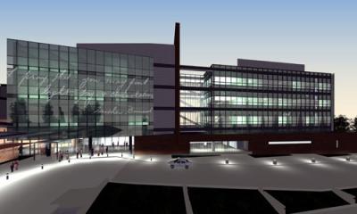
Architecture Description St. Joseph Hospital of Orange Patient Care Center & Facility Service Building is built within the Saint Joseph Hospital Campus serving the healthcare needs of the Orange county community. The Patient Care Center is linked to the main hospital through an underground tunnel to further serve the patients’ needs. The patient care center consists of two towers joined together with a central courtyard. The Patient Care Center consists of operating rooms to expand the surgical capacity of the main hospital. Operating rooms are equipped with latest innovative technology and medical equipment. To help further serve the main hospital, the Patient Care Center also has additional room for incoming patients and rooms for patients requiring intensive care. The Patient Care Center has a central sterile plant located on the basement level with all the MEP equipment. The first level of the hospital consists of surgical rooms, administrative rooms and the lobby. The upper floors are separated by the central courtyard. The west side consists of patient rooms and the east side consists of intensive care units. The remaining mechanical equipment is located on the roof level. Structural braced frames are accentuated through exterior glazing. Exterior glazing also has an etched inspirational message from one of the hospital’s highly recognized founders that is viewable to incoming patients. Typical floor to floor height is 12’-0” to 15’-0” while the first floor is 18’-0”. Applicable Codes
Zoning Under the Planning Act of the State of California the zoning map of Orange, CA classifies the project site as a Public Institution District.
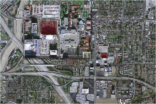
Fig1. Satellite location of the Patient Care Center
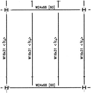
The building envelope was a key element to the Patient Care Center. It assembles modern style architecture but also projects an effective inspirational message through the tempered glass curtain wall. There are also precast panels located on the lower level of the Care Center, which illustrates a base to an “inspirational piece of scripture.” Structural steel cross bracing is also illustrated though the exterior glazing curtain wall, while being framed top and bottom with aluminum panels. The obstructive mechanical equipment on the roof is screened by aluminum panels that express a fine vertical ending to architecture and message revealed throughout the building. The west tower is bookend at the courtyard with a precast concrete wall that rises 14’-7” from the aluminum screen on the roof. There is a primary roof system of the Care Center which consists of concrete on steel decking. The Care Center uses two roof decking configurations, both use 3” decking but concrete thicknesses of 6” and 4.5”. Both configurations provide a 2 hour fire rating and use R-30 isocyanurate insulation board. To further keep the water out, a protection mat is laid on top of the insulation then covered with gravel ballast. Primary Engineering Systems Structural System Floor Framing There are minor variations to the floor framing through the Patient Care Center. The typical floor system is a composite steel framing using lightweight concrete and a total thickness of 6¼”, 3” composite deck is used with 5” long, ¾”diameter shear studs for composite action. The typical infill beam is a W16x31, 30’-0” long spaced at 10’-0” on center, which frame onto a W24x68 30’-0” long. Variations from the typical floor system are based on the use of the space. Light weight concrete was used in the typical steel deck configuration to reduce shear and overturning moment during seismic events.
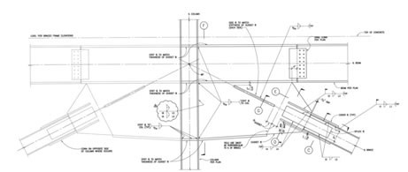
Fig2. Typical 30’-0”x30’-0” bay located on Levels 2, 3 and 4First floorThe floor framing plan on the first floor differs from the rest due to different loading criterion used. Typical infill members used are W18x35 framing into W24x68 girders. Composite steel framing is used with normal weight concrete and a total thickness of 7½”, 3” composite deck with 5” long, ¾“ diameter shear studs. Second floorThere is a central courtyard which is supported by the second floor framing system. Due to the high loading W21x111 infill beams are used which frame into W30x148. A composite steel framing system is also used with normal weight concrete and a total thickness of 9”, 3” composite deck with 5” long, ¾“ diameter shear studs. RoofDue to the location of air handling units on the roof, members with a higher loading capacity are required. Therefore the member sizes change to a W18x40 for beams and W24x84 for girders. A 9” composite steel system exists similar to the second floor courtyard but covered with rigid insulation. Lateral Resisting SystemThe lateral system consists of 6 sets of braced frames located both along the N-S and E-W planes. It ranges from 2 bays to as long as 6 bays framing vertically to the roof of the structure. These braces are supported by shear walls at basement level. The braced frames are typically X-bracing while a whole set running E-W is diagonally braced. Both configurations are considered concentrically braced frames. X-Braced frames are a TS shaped with a gusset plate slipped in and welded. The gusset plate is then welded onto the column and beam, allowing the brace to buckle out of plane to dissipate energy at time of an earthquake. While diagonally braced member consists of a W Shape section which has its web and flanges welded to a plate which are all then welded onto the gusset plate. The plates attached to the flange are slipped in the gusset plate and welded.
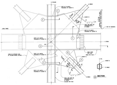
Fig3. Diagonal Brace Connection Detail
Fig4. X Brace Connection DetailFoundation SystemGravity columns at the basement level are supported by concrete footings. These footings range depth from 1’-6” to 3’-6” and their size ranges from 2’-0”x2’-0” to 16’-0”x16’-0”. While the shear walls are supported by continuous deep footings typically 5’-0” deep and 7’-0” wide from each face of the wall. The majority of the foundation is considered shallow as advised by the geotechnical engineer. While the main entrance canopy is supported by piles capes each connected to 4 piles. Columns There are two columns sets per gridline intersection which are usually spliced at 5’-0” from the Level 2. Typical columns sizes are W14x99 on the upper levels (Level 2 to Roof); while the lower columns are W14x145 or W14x132 depending on location and there loadings. Columns existing in the braced frame are usually W14x145 except the end columns which are W14x211 on the top and W14x311 at the bottom. These columns have greater strength capacities due to the excess axial tension and compression they carry from the bracing system induced moment. ConnectionsBeams and Girders are typically connected to each other using bolted connections on the beams with steel plates and welded on the girder. The gravity girders have similar connections to the columns, where a shear plate is welded on the column flange. Electrical Lighting Mechanical The Patient Care Center is equipped with 8 air handling units located on the roof. Air handling units supply 36,000 to 70,000 CFM. Due to the clean air requirements the hospital is equipped with 2 unfired clean steam generators that humidify the air supply. To meet the patient’s comfort each room is equipped with a terminal air unit that is self controllable. Since the Patient Care Center is located on a hospital campus, chilled water and steam is supplied from the main campus chiller and steam generator; used to condition the water supply. Fire Protection Transportation Telecommunications Special systems
|