structural option
granby tower
515 granby street...norfolk... virginia
this is a student-generated capstone project e-portfolio (cpep) produced in conjuntion with the ae senior thesis e-studio |
| |
| home |
| student bio |
| building statistics |
| thesis abstract |
| technical assignments |
| thesis research |
| thesis proposal |
| presentation |
| final report |
| reflection |
| senior thesis e-studio |
user note: while great efforts have been taken to provide accurate and complete information on the pages of CPEP, please be aware that the information contained herewith is considered a work-in-progress for this thesis project. modifications and changes related to the original building designs and construction methodologies for this senior thesis project are solely the interpretation of tom yost. changes and discrepancies in no way imply that the original design contained errors or was flawed. differing assumptions, code references, requirements, and methodologies have been incorporated into this thesis project; therefore, investigation results may vary from the original design. |
contents
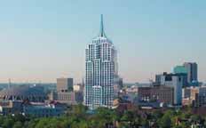
building name - Granby Tower
location - 515 Granby Street, Norfolk, Virgina
building occupant name - 515 Granby, LLC.
building function - mixed-use (luxury condominiums, offices, shops, and parking garage)
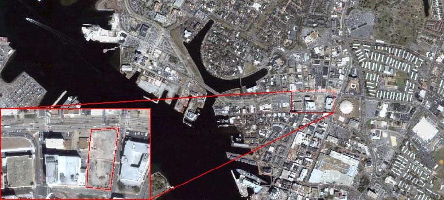
site area - 2.32 acres
building area - 781,479 square feet
tower - 475,548 square feet
garage - 185,305 square feet
town home - 21,791 square feet
retail - 17,046 square feet
office - 17,543 square feet
height - 34 total levels & 137.2 meters to top of spire
dates of construction - July 2007 - September 2009
project cost - $181,000,000
delivery method - guaranteed maximum price
owner - 515 Granby, LLC.
project management - Turner Construction Company
architect - Humphreys & Partners Architects, LP.
structural - Abiouness, Cross and Bradshaw, Inc.
mep - Jordan & Skala Engineers, Inc.
civil - LandMark Design Group
landscape - Ann P. Stokes Landscape Architects
interiors - HPA Design Group
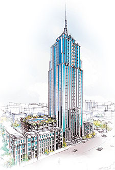
granby tower is a post modern high-rise with cast in place concrete shear walls and columns, two-way post-tensioned floor slabs, and a 125 foot spire that marks the highest point in Norfolk. the post-tensioned slabs allow for a more open floor plan with larger spans between columns and higher floor to ceiling heights in residential spaces. central shear wall cores house elevator shafts, stairwells, and mechanical duct work thus providing all leasable space with views of downtown norfolk and the elizabeth river.
applicable codes
2000 international building code
2000 virginia uniform statewide building code
2000 international fire code
2000 international mechanical code
2000 international plumbing code
2000 international electric code with 1999 national electric code
zoning
residential - R-2
amenities - A-3
office/leasing - B
retail - M
garage - S-2
historic
historically granby street was the premier shopping, dining, gathering and theatre corridor, and these luxuries were supplemented by the direct connection to the elizabeth river waterfront. the conveniences of granby street fell out of favor in the 1960’s as suburban development between norfolk and virginia beach promised bargain shopping malls. due to the decline in popularity of a very important landmark and cultural center, city officials began reviving the city center in the 1970’s and are still working to regain the prestige that granby street held in the early 1900’s.
building envelope
the exterior cladding system for granby tower consists of a mixture of materials including aluminum composite materials panels, synthetic concrete, stucco, and curtain wall glazing. aluminum composite materials (ACM) panels are pre-shaped, pre-painted, lightweight, durable finishes that are used throught the exterior to contrast the rough stucco finish. stucco is used on most lower floors while synthetic concrete is used for roofs, upper floors, and store fronts. curtain wall glazing is used throughout the building with aluminum frame and laminated glass railing at all decks.
structural
the lateral force resisting system at granby tower consists of dual, ordianary concrete shear wall cores that house the elevators, stairs, electrical and gas lines, and fire dampers. The first 6 levels consist of 24” walls with a 28-day compressive strength, f’c = 8000 psi, while the remaining levels consist of 14” shear walls with compressive strengths of 6000 (Levels 7 through 23) and 5000 psi (Levels 24 through 34).
the floor framing system is a two-way flat-plate post-tensioned slab with minimal drop panels to capitalize on floor to ceiling height. all slabs are designed with a 28-day compressive strength (f’c) of 5000 psi, and the first 7 levels of the tower require 9” slabs while the remaining levels are designed as 8” slabs. tendons for post-tensioning will be ½” diameter (ø), 7-wire, low relaxation strand, fully encased in grease with a minimum sheathing thickness of 50mm. maximum sag for tendons will be 5 ½” and supported by chairs or bolsters. post-tensioning will occur when the concrete has reached 75% of its designed f’c, and all of the uniform tendons shall be stressed before banded tendons. Uniform tendons are even distributed through the north-south (long) direction with a maximum span of 26’ while banded tendons run east-west (short direction) along column lines with a maximum span of 30’.
gravity columns are laid out on a fairly regular grid with the largest bay at 26’x30’. roughly 32 columns run the full building height with some of the exterior columns terminating at the buildings first significant set-back on the 29th floor. most columns are square reinforced columns with rebar ranging from #7 to #10, but rectangular columns with the strong axis in the short building direction (east-west) are architecturally situated in central east and west apartments. columns above the parking garage (Level 7) are designed with f’c = 5000 psi, and columns between Level 6 and the foundation are designed with f’c = 6500 psi. Some drop panels are required on upper floors as column sizes decrease and/or slab edges become flush with exterior columns.
roughly 1200 piles were driven throughout the site with 255-14” square, precast, pre-stressed concrete piles (SPPC) at 90 feet deep with 140 ton capacity supporting the shear wall cores. due to the lateral forces seen by the shear walls, the outer 156 piles are designed for tension. the pile cap supporting the shear wall is 10 feet thick with f’c = 5000 psi and #10 and #11 reinforcing on top and bottom, while all other pile caps will be designed with an f’c of 4000 psi and # 7 and #8 reinforcing. the slab on grade is 5” thick, reinforced with 6x6-W2.9xW2.9 welded wire fabric over a 10 mil polyethylene vapor barrier. The geotechnical engineer specified the slab to be placed over 4” porous fill with less than 5% passing the No. 200 sieve to act as a capillary barrier. The slab should also be “floating” in the sense that it is not rigidly connected to columns or foundations to reduce cracking.
construction
notice to proceed was issued on 2 july 2007 and a duration of 863 days is expected to carry construction into november 2009. turner construction company will lead the construction and holds a guaranteed maximum price contract with the owner, 515 granby, l.l.c for $181,000,000. pile driving began in july and was roughly 45% when construction was paused in september due to funding issues. when funding is in place, pile driving will continute (initial expected completion of december 2007) and then construction of foundations for tower and residential buildings will commence. while all tower elements are cast-in-place concrete, residential town-homes utilize some wood framing.
electrical/lighting
the main electrical distribution system consists of two 208/120 volt, 3ø,4-wire busways. bus 1 serves 114 tower units from the 17th to 31st floors with meter centers on floors 18, 21, 24, 27, and 30. since units are measured individually and bus taps occur every 3 floors, bus taps range in size from 1000/3 to 400/3. the total expected load for bus 1 is 2455.4 amps. bus 2 serves 139 tower units from the 2nd to 16th floors with meter centers on floors 3, 6, 9, 12, and 15. bus taps range in size from 1000/3 to 600/3 and bus 2 has a total expected load of 2843.2 amps.
the main house system operates at 480/277 volts and primarily services mechanical equipment on the 32 floor, spire lights, corridor receptacles, and window washing equipment. transformers are located on floors 1, 2, 9, 21, and 32 for use in residential floors or mechanical system controls. the emergency house system (also 480/277 volt) services elevators, core exhaust fans, corridor lights, fire dampers, and pumps and also workes in conjunction with a 500KW diesel generator.
typical unit lighting consists of compact fluorescent recessed downlighting in kitchen and living spaces while bathroom and vanity spaces utilize wall mounted 100W incandescent lamps. stair and corridor lighting consists of two lamp fixtures, and garage lighting lighting utilizes metal halide lamps.
mechanical/plumbing
granby tower utilizes a water loop heat pump system to distribute water for heat exchange at each unit. all units are equipped with vertical or horizontal mounted water source heat pumps in order to control heat per unit. due to norfolks mild climate, tempered water pumps send water to boilers on the 32nd floor to heat water to 60F during heating situations. for cooling situations, heat exchangers work in conjuction with cooling water pumps and the cooling tower which is located on the 32nd floor and is open to the 34th floor.
conditioned air is supplied to hallways at each floor by two large air handlers on the 32nd floor through ductwork in the shear wall cores. since there is no return ductwork, hallways are positively pressurized to force air into the units. stairwells are also postively pressurized to force smoke out in a fire.
water supply is separated into two zones, high and low. the low zone supplies water in 2.5" pipes to the first 6 floors using city pressure. the high zone utilizes a booster pump to distribute water to upper levels. pipe sizes range from 6" from the booster pump to 4" before splits and 2" throughout each floor.
transportation
granby tower has 5 elevators in use with 3 main elevators in service from the 1st to the 30th floors. these passanger elevators can be serviced on the 31st level. a freight elevator will travel 33 floors (1st to 32 floors) and a hydro elevator will travel between the first and upper first floors. the freight elevator can be serviced on the 32nd floor and the hydro elevator on the 2nd floor.