MEGHAN GRABER | CONSTRUCTION MANAGEMENT OPTION
| BUILDING STATISTICS | ABSTRACT | TECHNICAL ASSIGNMENTS | RESEARCH | PROPOSAL | PRESENTATION | FINAL REPORT | REFLECTIONS | MEGHAN GRABER |
| Note: While great efforts have been taken to provide accurate and complete information on the pages of CPEP, please be aware that the information contained herewith is considered a work-in-progress for this thesis project. Modifications and changes related to the original building designs and construction methodologies for this senior project are solely the interpretation of Meghan Graber. Changes and discrepancies in no way imply that the original design contained errors or was flawed. Differing assumptions, code references, requirements, and methodologies have been incorporated into this thesis project; therefore, investigation results may vary from the original design. |
Building Statistics
Part 1
General Building Data
Building Name: Integrated Science Center - Phase I & II
Location: College of William & Mary - Williamsburg, VA
Building Occupant Name: College of William & Mary biology, chemistry, and psycology departments
Building Function: Classrooms, teaching and research laboratories, and administrative spaces
Size (total square feet): Expansion - 120,000 GSF ; Renovation - 41,000 GSF
Number of Stories: 3 stories plus a mechanical penthouse story above grade and one story vivarium below grade
Primary Project Team:
-
Owner: College of William & Mary - Williamsburg, VA
-
CM: Gilbane Building Company - Richmond, VA
-
Design Team: Moseley Architects - Virginia Beach, VA; Payette Architects - Boston, MA; SST Planners - Arlington, VA
-
Civil Engineer: Clough, Harbour & Associates LLP - Richmond, VA
-
Mechanical, Electrical, and Plumbing Engineer: Affiliated Engineers Inc. - Rockville, MD
-
Structural Engineer: McPherson Design Group P.C. - Norfolk, VA
Dates of Construction: January 2006 - March 2009
Project Cost: $47 million
Project Delivery Method: Design-Bid-Build for a CM at risk
Architecture
Architecture:
This project includes the construction of a new, high-tech laboratory building as well as the renovation of existing spaces. The addition contains research and teaching laboratories, lecture halls, classrooms, instrument rooms, and office spaces. William and Mary's intent is to upgrade the outdated departments of chemistry, biology, and psychology, replacing facilities over 30 years old. The college aims to become a national leader in research and teaching facilities in these departments.
Founded in 1693, the College of William and Mary is the second oldest institution of higher learning. In order to preserve the historic atmosphere, the college has developed a "vision plan" as guidelines for the insertion of new structures. This stresses the importance of preserving the architectural configuration and character of the Old Campus. Therefore, the ISC building's appearance and facade was designed to match the brick style and color seen throughout the campus.
Major National Codes:
-
Virginia Uniform Statewide Building Code - USBC, 2003 Edition, Effective November 16,2005
-
Construction & Professional Services Manual, Commonwealth of Virginia ADAAG, Published July 23, 2004
-
The International Mechanical Code (IMC), 2003
-
The International Plumbing Code (IPC), 2003
-
The National Electrical Code (NEC), 200
-
The International Fuel Gas Code (IFGC), 2003
-
International Energy Conservation Code (IECC), 2003
Zoning: Assembly
Historical Requirements: None
Building Envelope:
The brick exterior wall system is comprised of 6" batt insulation that lines the space between two 5/8" gypsum board. The continuous air and vapor barrior is followed by 2" R-10 rigid insulation. A cavity drainage material is located between the insulation and the flemish bond face brick. Masonry ties fasten the brick to the facade, and continuous flashing with weeps extends 1/8" beyond the face of the brick for proper drainage.
The roof system consists of a metal roof deck followed by 5" of nailable vented R-20 insulation. An ice and water protection underlayment was placed before the stimulated slate roofing.
Part 2
Primary Engineering Systems
Construction:
The College of William and Mary is interested in upgrading its out‐of‐date chemistry, biology, and psychology departments by replacing buildings over 30 years old with top‐of‐the‐line facilities. This joint project includes the addition of a new, high tech laboratory building as well as the renovation of the existing Rogers and Millington Halls. The entire addition/renovation project is broken into five phases. Phases I and II were bid on together and awarded to Gilbane Construction Company. The remaining three phases (Phases III‐V) are still in the schematic design stage.
Phase I includes the addition of the 3 story, 116,500 SF Integrated Science Center. This building has a mechanical penthouse located on the 4th floor and an animal holding area in the basement. Once the new addition is complete, Gilbane will work with the college to transition people and equipment out of the existing building into their new home. Once vacant, the existing buildings will be gutted and renovated. Phase II includes the renovation of the exiting, 2 story, 42,500 SF Rogers Hall only. Careful attention is required to move expensive equipment and hazardous materials, and hit certain academic dates.
Demolition:
The demolition of interior partitions, ceiling assemblies, casework, and flooring materials in the existing Roger’s Hall (except in the auditorium area) is required without jeopardizing the structural integrity of the building. Coordination between demolition work and new work is necessary for the structural, plumbing, mechanical, and electrical systems. Asbestos was detected in samples of vinyl floor tile, black duct mastic, panels of a laboratory fume hood, white pipe mastic, and corrugated cementitious panel from the rooftop HVAC cooling tower therefore abatement was required before commencing work.
Structural:
The structural system for the Integrated Science Center consists of structural steel. This steel structure provides the building with long spans and column free spaces. W18x35s and W12x16s are the most typical transfer beams. Column sizes vary from W10x33s to W12x65s. The supported floor system consists of a 5” lightweight concrete slab on a 1-1/2” 22 gauge composite deck. Braced frames and moment resisting connections resist lateral forces on the building.
Mechanical:
A mechanical penthouse is located on the fourth floor of the ISC addition. It contains five (5) AHUs with a max of 40,700 cfm. The existing Roger’s Hall has its own mechanical room located on the 1st floor of the east end of the building. The original room was gutted, reconstructed, and new equipment was installed. It contains two (2) AHUs with a max of 29,900 cfm. The constant volume AHUs distribute through galvanized sheet metal duct and supplied to rooms through registers and grilles. Two 480 V boilers are located in the boiler room (ground floor of ISC building) along with an expansion tank and various heat pumps. This specialized laboratory building features a lab waste neutralization system, compressed air system, vacuum piping system and lab/acid waste piping.
Electrical:
A 2000 kVA transformer (35KV/480V/277V) is located on the ground floor of the ISC building. There are ten (10) dry type transformers (25kVA‐300kVA) throughout the building and they are NEMA TP‐1 rated. These three phase transformers are 60 Hz with a 480 V delta primary and 208Y/120 V secondary. There is one switchboard rated to withstand fault current of 100,000 amperes. Redundancy is provided by emergency power generation. Emergency/standby power will be supplied by a 1250 kW diesel engine generator. The demand load estimate for this project is 4,253.9 kVA.
Lighting:
Different sized fluorescent, incandescent, and HID lamps are used for various types of lighting fixtures. The majority of the labs, classrooms and offices are illuminated by recessed, ceiling grid mounted, fluorescent lights. Suspended mounted fluorescent lights are used in the bathrooms. The corridors contain wall mounted fixtures and recessed incandescent lighting is located in the lobbies.
Additional Engineering and Engineering Support Systems
Support of Excavation:
Permanent steel sheet piles and tie‐back anchors were installed at the interface with the existing structures to facilitate the required excavation of the new addition. This system would potentially eliminate any surcharge loads from the existing building foundations on the basement walls of the new structure. Although the basement elevations are above the current ground levels, it is likely that some soils may transport water during wet seasonal conditions. The basement walls were waterproofed and a geocomposite drainage medium was applied to the outside of the walls. The wall drainage material is connected to a storm sewer system.
Foundation:
The ISC addition is supposed by a shallow foundation system (spread footings) in conjunction with ground reinforcement measures. The Geopier Intermediate Foundations System is used to reinforce the foundation soils on this site. This process first involves drilling a cavity. Layers of aggregate are then placed into the drilled cavity in thin lifts of one-foot compacted thickness. A patented beveled tamper rams each layer of aggregate using vertical impact ramming energy. The tamper forces aggregate laterally into the cavity sidewalls resulting in exceptional union with surrounding soils. Following installation, this system can support the designed spread footings. The Geopier elements provide bearing support, settlement control, significantly higher resistance to sliding and uplift.
Masonry:
This building has brick veneer/metal stud exterior walls. Galvanized steel shelf angles transfers the weight of the masonry back to the structural frame. Masonry ties at 1’‐4” O.C. secure the brick veneer to the backup system. The brick for the Phase I addition is a Flemish Bond pattern to match the adjacent dorm construction. The brick for the Phase II renovation is also a Flemish Bond pattern to match the existing Roger’s Hall. The ISC’s ground floor vivarium contains 6” CMU interior partitions.
Fire Protection:
ISC and Rogers Hall will be equipped with a fire alarm and sprinkler system. Standard Orifice quick response sprinklers will be installed throughout the entire building. This is a wet sprinkler system. Basket guards will be provided on all exposed on all exposed sprinklers in equipment rooms, electrical rooms, and telecom rooms. Wall mounted pull boxes, audible alarms, and strobe lights are located in the corridors and easy to see spaces.
Transportation:
There are two hydraulic passenger elevators in the ISC building. The one located at the north end of the ISC is a 4,500 lb capacity, 4 stop elevator which services the ground through third floors. The south end one is a 3,500 lb capacity, 5 stop elevator which services the ground through fourth floors. The fourth floor is where the penthouse is located. Both cars have a 150 fpm speed capability.
Telecommunication:
There are data/communication outlets located in all the laboratories and classrooms. They are located on the floor, in the casework, or wall mounted. Faculty offices contain wall telephone outlets. Wireless LAN antennas and junction boxes are located in the ceiling for internet connection throughout the building.
PROGRESS PHOTOS
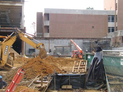
DEMOLITION
GROUND FLOOR CMU
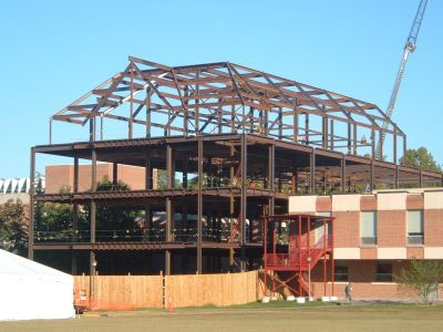
STEEL FRAMING
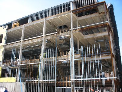
METAL STUDS
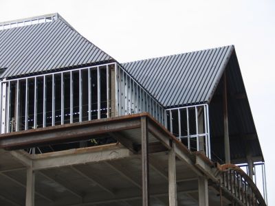
STIMULATED SLATE ROOF
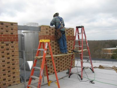
BRICK EXTERIOR
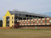
SOUTH FACADE DURING CONSTRUCTION
SOUTH FACADE END DURING
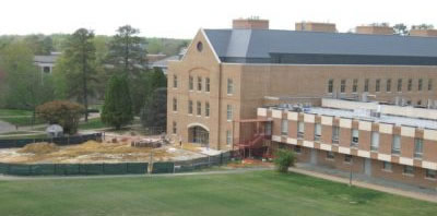
CLOSEOUT OF PHASE I
SENIOR THESIS | THE PENNSYLVANIA STATE UNIVERSITY | ARCHITECTURAL ENGINEERING | AE LAB | CONTACT MEGHAN GRABER
This page was last updated April 27, 2009, by Meghan Graber and is hosted by the AE Department @ 2008