| |
| Home |
| Student Biography |
| Building Statistics |
| Thesis Abstract |
| Technical Assignments |
| Thesis Research |
| Thesis Proposal |
| Presentation |
| Final Report |
| Reflection |
| Senior Thesis e-Studio |
|
![]()
Building Statistics
| building name | IAC/InterActiveCorp Headquarters |
| location | 555 W. 18th St, New York, NY |
| building occupant | IAC / InterActiveCorp |
| function | Office building |
| size | 130,000 sq feet |
| number of stories | 11 (1 below grade) |
| client | The Georgetown Company, New York, NY |
| tenant | IAC InteractiveCorp, New York, NY |
| design architect | Gehry Partners, LLP, Los Angeles, CA |
| executive architect | Adamson Architects, New York, NY |
| general contractor | Turner Construction, New York, NY |
| structural | |
| mep | Cosentini Associates, New York, NY |
| electrical | Brandston Partnership Inc., New York, NY |
| environmental | Blasland, Bouck & Lee, Inc, Chicago, IL |
| acoustics | Shen Milson & Wilke, Inc, New York, NY |
| curtainwall | Israel Berger & Associates, New York, NY |
| foundations | Langan Engineering, New York, NY |
| construction dates | June 2004- March 2007 |
| overall building cost | Information disclosed at owner's request |
| project delivery | Guaranteed Maximum Price |
| codes | New York City Building Code (the former version- a new code has since been established effective July 2008) |
| zoning | Commercial District, Section C6-3 from Zoning Map 8B of NYC Planning Commission (part of the Special West Chelsea District Purpose) |
| historical requirements | None |
Construction:
The method of construction for this project was guaranteed maximum price. Construction began in June 2004 and was completed in March 2007. Turner Construction was the general contractor for the project. A 3D modeling package called Catia, which is a Gehry Technologies product, was used to coordinate the building systems’ designs.
While the superstructure went up fairly quickly (2 floors a week), the major problem with construction arose with the foundations. The IAC Headquarters sits very close to the Hudson River and had very poor soil conditions as well as contamination problems from a former factory on the site. Caissons needed to be used to tie in to the rock in order to support the superstructure.
Another interesting aspect of the construction was the installation of the curtain wall. Each of the units were different in shape and curvature so they were cold-warped (bent) in the field before being installed into place and clipped in 4 places.
Lighting/Electrical System:
The building runs on a 208Y/120V 3 phase, 4 wire electrical system. There are 2 main 6000 amp switchboards in the cellar that power the panel boards on each floor. There is a 4000 amp full neutral central bus duct that feeds each of the local panel boards. A 800 KW emergency generator is on the 10th floor (mechanical penthouse level). It serves the fire pump and 600A auto-transfer switch in case of emergency. The electrical supply (from Con Edison) is along the west side of the building.
Alcove lighting follows along the perimeter of each floor. There are also hanging indirect lighting fixtures in the shape of a disc that hang over each workstation. At the outdoor terrace, there are recessed lighting fixtures. Lighting drawings and full specifications are not available at this time, so further information is in not known.
It is also important to note that there is an open-office layout with the intent that all of the spaces other than the transportation and services core will receive natural day lighting, cutting down on the daily lighting loads.
Mechanical System:
Constant air is delivered to air handling units on each floor. These units range from 2500 cfm all the way up to 28000 cfm. The system appears to be set up for a VAV system; however, the mechanical plans available do not detail the systems for distributing the air from the fan room to the remainder of the space. It can only be assumed that that work was later contracted out for the tenant. Fintube radiators run along perimeter of the building at each floor.
Fire Protection:
There is 3” conduit between fire alarms. The main fire alarm panel is mounted in the concierge desk on the ground floor. Wet sprinklers are spaced 6’-0” on center around the perimeter at each floor and within and around the core. A 750 GPM auto fire pump is there, as well as dry sprinklers in the emergency generator room.
Transportation:
There are 4 private elevators that are all adjacent to the elevator lobby and run at 350 feet per minute. These elevators are 6’-8” by 5’-5” inside cab dimensions. Three of the elevators went from the cellar to the 9th level (with a net lifting capacity of 3,500 lbs), while the northeast elevator went all the way to the 11th (with a net lifting capacity of 4,000 lbs). There are 2 primary stair wells. Stair #1 is east of the elevator core and exits on the ground floor to the east. Stair #2 is northeast of the elevator core with an exit along the north façade. Stair #1 extends all the way from the cellar floor to the 11th, while Stair #2 goes from the ground floor to the 10th. There are also other stairways that connect the basement to ground, ground to 2nd floors, and 6th to 7th floors. Additionally, a ramp for vehicles goes from the west side of the ground level of the building down to a parking area in the basement.
Telecommunications:
Four inch EMT conduit sleeves distribute the carrier services to the floors. There is a telecommunications room on each floor stacked on top of the other. There are 6 pullboxes on the ground and cellar floors.
Security System:
The IAC Headquarters has a security system of cameras, card readers, and personnel. Cameras are located near the entrances as well as in the garden area. Card readers are also heavily used. Card access is necessary to get to the elevators or stairs. Also, access to certain conference areas and the roof is only by card access.
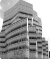
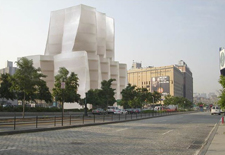
Architecture:
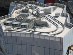
TheIAC/InterActive Corp Headquarters is the first commercial office building designed by Frank Gehry in New York City. This sculptural, fully glass-clad building is intended to be reminiscent of boat sails at full mast. It is the headquarters for IAC, which is a leading internet company that has over 35 brands such as match.com, ask.com, gifts.com, and collegehumor.com. The cellar has a small parking area with cars jacked up with machinery and stored during the day to save space and a ramp leading up to the first floor. The first floor opens to an immense lobby space. Behind the lobby desk and facing 11th Avenue is a 120’ x 11’ high video projection wall, which is the largest high resolution video wall in the world. The lobby is sparsely furnished with Gehry-designed wicker seating, also having the curved shape. This lobby has been used for company functions as well as has been rented out for private functions. There is also a mail room, loading dock and mechanical space on this ground level. The remaining 2nd through 9th floors is office space for the 400+ IAC employees, designed in an open floor plan manner. On the 6th floor, the executive floor, there is an outdoor terrace with benches, tables and plants. The 10th floor primarily contains the mechanical penthouse. On the roof there is large window washing equipment.
Building Envelope:
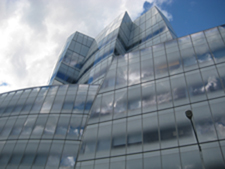
The IAC Headquarters is completely clad with glass curtainwall that was manufactured by Permasteelisa. It consists of over 1,400 exterior glass panels, each in unique shapes. The curtainwall is fritted at differing gradients to provide for privacy, but also to act as a natural shade from the sun. It is composed of laminated double glazing panels with aluminum mullions. The roof is composed of concrete pavers on setting blocks, filter fabric, 3 ½” rigid insulation, a waterproofing membrane, and 1 ½” concrete topping, all resting above the concrete slab. I am currently still researching into the glazings and coatings for the glass as well as the type of water proofing membrane, since this information is not readily available without the specifications.
Structural System:
The IAC/InterActiveCorp is a concrete building due primarily to its irregular shapes and the ease of forming concrete into various shapes. It is a cast-in-place concrete flat slab building with irregular edges that cantilever out and circular concrete columns that often slope from floor to floor. Most of the columns slope (in the same direction) because the floors set back as they get higher and sloped columns allow for them to be placed in desirable locations. This causes significant torsional rotation of the building structure, however.
Because of the sloping columns, none of the structural floor plans are the same, though they differ only slightly between most of the floors. The basement floor is a 24” thick pressure slab with f’c= 5000 psi and #6 @ 10” o.c. E.W. top and bottom bars. The slab thickness for the first through fifth floors is 12” with primarily #5 @ 12” o.c. top and bottom bars in the 5000 psi strength concrete. At the sixth floor, where the building sets back (leaving room for an outdoor terrace), the slab thickness is 24”. The concrete strength is 5000 psi as well, but the top and bottom reinforcing bars are typically #7 @ 12” o.c. It is at this location that the column layout changes much more drastically. This thicker slab acts as a transfer diaphragm to transfer the loads from the upper columns down to the lower ones. The seventh through roof levels have similar slab properties to the first through fifth floors, except that it has a slab thickness of 14”. An unusual aspect of the slab reinforcing details is that unlike typical American Concrete Institute standard details which involves rotating rebar to match specific edge angles, the structural designers chose to design the reinforcing steel in the north-south and east-west orthogonal directions.
The columns carry the gravity loads while the shear walls of the elevator and stair cores carry the lateral forces from wind or earthquake. They have an f’c of 5950 psi. The columns in the basement are primarily 28” in diameter for the perimeter columns and 34” to 38” in diameter for the interior columns. This range of column diameters is fairly consistent throughout the ground through fifth floors, but at the sixth floor the sizes are reduced to 20” to 24” typically. As mentioned above, the shear walls are in the elevator and stair cores. These shear walls tend to be between 12” and 14” thick. They are reinforced by #4’s at 12” in the vertical and horizontal directions.