 |
|
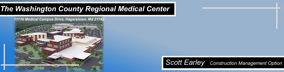
Building Statistics PART I GENERAL DATA: Building Name: Washington County Regional Medical Center
Dates of Construction: March 2008 - December 2010 ZONING: Hospital: Use Group I-2 (Institutional Hospital) CODES: 2003 International Building Code (IBC) (For total building except seismic design) ARCHITECTURAL DESCRIPTION: Washington County Regional Medical Center (WCRMC) is a new hospital to replace the existing Washington County Hospital that was located in the downtown area. The new medical center will be built on an existing medical campus, Robinwood Medical Campus, which includes a two story outpatient procedures facility. WCRMC was designed to be a state of the art facility to assist in providing top quality patient care. The new medical center has 275 single-patient rooms with private bathrooms, an expanded emergency department with 53 treatment rooms, two trauma and two cardiac rooms, as well as private and separate corridors for patient transport and public visitation. The site the new medical center will sit on is sloped creating the first level to be below grade on one side of the building and on grade on the opposite side. The second level adds the administrative wing, or the "link", to the building footprint. The link will attach directly into the existing Robinwood building creating a flow between the two facilities. The second level also carries the main part of the building through it. The link and the patient bed towers continue to the third level where the link stops and the three bed towers continue two more levels creating the main vertical elements of the building. The building consists of three different types of veneer; brick, precast architectural panels, and exterior glazing. The brick is mainly located on the link to the existing facility and various other lower levels of the medical center. The precast panels are primarily located on the patient bed towers with the exterior glazing spread throughout all sections of the building. A typical wall cavity is used behind these veneers. It consists of rigid steel framing supported by the steel structure. The roof system throughout all areas of the medical center is fairly consistent. It is made up of a ballasted single ply roof membrane on rigid insulation, all of which sits on metal roof deck supported by the steel structure. The roof also contains a helipad for the transportation and reception of patients flown by helicopter. This particular section of the roof is a 4" concrete slab on rigid insulation with a reinforced hot applied membrane as the cover. Also a small section of the building contains a standing seam metal roof on rigid insulation and oriented strand board. This is located over the religious services section of the building and provides a distinct difference in the appearance to create a visually separate space. PART II CONSTRUCTION CHALLENGES (PROJECT SITE): The site is underlain by the Conococheague Limestone formation and the site soil is primarily composed of silty clay, clayey silt, and silt with various amounts of sand and rock fragments. The soil located on the site takes an abnormally long time to dry out and becomes saturated easily. The subsurface testing concluded that there was no real concern with subsurface water condition because the test borings performed without rock coring were dry both during drilling and at the completion of the drilling operations. This poses challenges for the site work crew especially when it rains. The site can become particularly muddy and the saturated soils need to be handled properly. STRUCTURAL SYSTEM: The medical center has a deep foundation system to support the five story bed towers. The foundation system is comprised of 150 caissons. The caissons must bear on rock with an allowable service load bearing pressure of 80,000 pounds per square foot. The structural system is comprised of a steel frame of wide flange columns and beams. There are not too many typical sizes of steel because of the unique design; however, the bed towers are comprised mainly of three different sections. They are W21x44, W18x35, and W12x16. Some typical sizes throughout the other sections of building are W16x31, W14x22, and W16x26. There are also other areas of the building that use hollow steel sections for miscellaneous steel framing. There are two different primary bracing systems used in the steel frame. The first is a vertical chevron style brace. This style of bracing is used in the highest sections of the building that extend from the foundation through the vertical elements of the stair towers. The other type of bracing is a form of cross bracing. This type of brace has two elements. The first beam extends one full diagonal of the frame while a second only goes from one corner to the midpoint of the full diagonal piece. All the structural concrete on the project will be cast in place. These items include the foundation walls, footings, grade beams, and the slab on grade and slab on decks. A steel formwork system is used for foundation walls and a stick-built plywood forming system is used for the footings and grade beams. The decks, typically 3 1/4" lightweight concrete with 6x6 - W1.4xW1.4 welded wire fabric, are on 3", 20 gauge composite metal decking with shoring on the deck below. The slab on grade is a 5" concrete slab with 6x6 - W2.1xW2.1 welded wire fabric on a 6" compacted granular fill. MECHANICAL SYSTEM: The mechanical system is comprised of three different elements and they are as follows:
The CUP is located in the service section of the building (first floor, plan south). It houses two 1,000 ton chillers and two 3,000 GPM cooling towers. The area also contains three high pressure steam boilers for hot water. The CUP has various pumps for the fire protection system as well as the mechanical system. The location of the CUP allows for ease of maintenance, service, and installation of the major systems. The first, and larger, of two dedicated mechanical rooms is located on the third floor of the south bed tower. There are three Air Handling Units (AHU's) located in this room of sizes 90,000, 100,000, and 110,000 CFM. These units serve separate sections of the building from the second through the fifth floors. The second of two dedicated mechanical rooms is located on the first floor, (plan) west side of the building. This room holds two more AHU's of 40,000 and 90,000 CFM. These AHU's serve various sections of the first floor departments. There are three other smaller AHU's located on different sections of the roof that serve dedicated spaces. LIGHTING AND ELECTRICAL SYSTEMS: The electrical system starts with service to the CUP where the main feed comes into the building. The electrical service feeds three separate electrical substations in the CUP. These substations are all 13.2 kV at 480Y/277V delivering 4,000 amps. The substations feed into different switchgear which then services separate sections of the building. The CUP location, as previously discussed, allows for easy maintenance and service for all the electrical switchgear and systems located there. There is redundancy built into the electrical system with two emergency generators, at 480Y/277 delivering 2,000 amps each, supplying key areas and emergency lighting in the medical center. The luminaries throughout the main areas of the building are fluorescent luminaries. However, there are also many different types of lighting in the operating rooms and other special procedures areas. FIRE PROTECTION SYSTEM: The fire protection system consists of three different types; a dry sprinkler system, a wet sprinkler system, and a foam monitor deluge system. They dry system is used in the main entrance canopy, the ambulance entry canopy, and the emergency patient entry. The foam monitor deluge system is used on the helipad. The rest of the building is a wet sprinkler system. TRANSPORTATION: There are a total of 13 elevators in the medical center. Elevators 1 through 3 are traction passenger/public elevators of 3,400 pound capacity. Elevators 4 through 6 are traction patient transportation elevators of 5,000 pound capacity. Elevators 7 through 9 are traction service elevators of 4,500 pound capacity. Elevator 10 is a hydraulic hospital elevator of 5,000 pound capacity and elevators 11 through 13 are passenger/service hydraulic elevator of 3,000 pound capacity.
|
 |
Contact Scott |