|
|---|
|
Note: While great efforts have been taken to provide accurate and complete information on the pages of CPEP, please be aware that the information contained herewith is considered a work‐in‐progress for this thesis project. Modifications and changes related to the original building designs and construction methodologies for this senior thesis project are solely the interpretation of George Slavik III. Changes and discrepancies in no way imply that the original design contained errors or was flawed. Differing assumptions, code references, requirements, and methodologies have been incorporated into this thesis project; therefore, investigation results may vary from the original design |
Building Statistics:
Architecture:
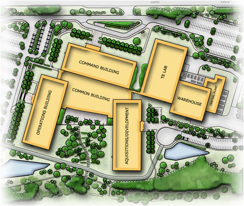
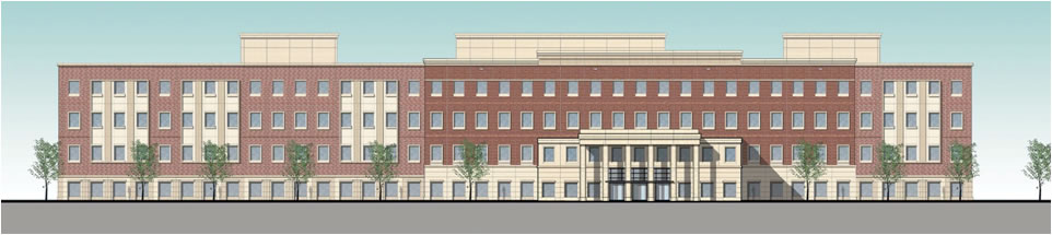
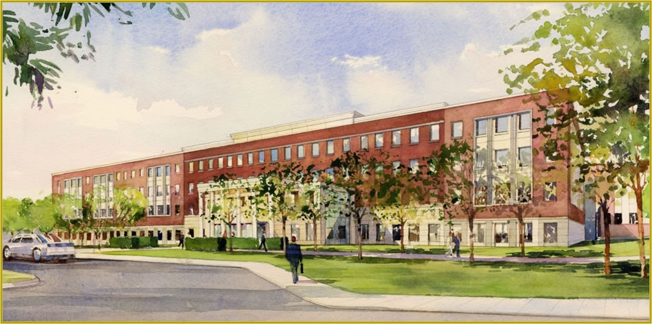
The site chosen for this facility was formerly a golf course at the Ft. George G. Meade Military Base in Ft. Meade, MD. Although the buildings were restricted by a four (4) story height limitation at Ft. Meade, the massing is such that the buildings are of relatively equal sizes to create a collegiate, campus feel.The architecture at the Ft. Meade military base is to meet the “Georgian Revival” architectural character. The approved design achieves the balance between this vernacular and that of a large scale modern Department of Defense facility.
The current versions of: National Fire Protection Association (NFPA); 54 – National Fuel Gas Code, 90a – Installation of Air Conditioning and Ventilating Systems, 96 – Standard for Ventilation Control and Fire Protection of Commercial Cooking Operations, 101 – Life Safety Code. Building Facade:
Roofing:
Sustainability Features:
Mechanical: TheCentral Utility Plant (CUP) is attached to the Warehouse, This building contains the Boilers and Chillers which distribute Campus chilled and heating water to the entire complex. The cooling loads are extremely high for this complex, while the heating loads are minor. The HVAC system selection for the DISA HQ was driven by the following criteria: The need for flexibility to accommodate future change The air systems served by the Central Utility Plant (CUP) were selected as follows: Office Space An Under Floor Air Distribution (UFAD) system to make full use of the 18” raised access floor and provide individual comfort control for the building occupants, and high energy efficiency when coupled with central roof level custom air handling equipment delivering low pressure air. The decision to place the AHU equipment on the roof rather than in AHU rooms is intended to maximize usable program area in the buildings. LabTo serve this high load area efficiently, a system of variable volume vertical air flow, Chilled Water (CHW) AHU’s designed specifically for use in data centers will be coupled with a direct injection outdoor air system to provide ventilation air at a constant dewpoint for humidity control. Common (Multiuse) Area:The lower floor contains the Cafeteria, Kitchen and Health/Wellness functions which are not suited for the use of a raised access floor. The HVAC systems for these areas are conventional overhead VAV with roof mounted AHU’s. The second floor contains the Conference Center and Training functions which utilize a raised access floor. These areas are also suitable for the use of a UFAD system, to maximize the comfort and energy efficiency of these areas. Special Use Spaces:These are mainly high load equipment areas, some without occupancy, some with people and equipment and some with people and normal computer loads. These areas are all on raised access floors and will be handled with chilled water Computer Room Air Conditioning (CRAC) units in combination with a direct injection outside air system to provide ventilation air at a constant dewpoint for humidity control; in general, other ventilation methods are also used for some areas. Mission Critical Spaces:Certain spaces are Mission Critical; therefore HVAC equipment for these spaces must operate on the generator when required, together with part of the central chilled water plant and key components of the Building Automation System (BAS), to enable the Mission Critical spaces to continue uninterrupted operation. In addition some HVAC equipment is required to be redundant to increase reliability.
Construction: To maximize the benefits of a design-build fast track process, the team implemented a process which completely integrates the design and construction at every phase of the disa hq. Labor saving methods such as reducing the number of steel pieces, precase exterior skin, pro-press mechanical fittings, and pre-fabrication. the short interval project scheduling system (sips) has been known to bring a production line approach to constructing buildings which require a great deal of repetitive activities. With over 800,000 sq. ft. of typical office space to construct, the disa HQ was perfect for this technique. each office floor will be conceptually divided into six areas of approx. 10,000 sq. ft. the work activities will be sequenced in one week intervals and a specific crew will be developed for each group of activities. the crews will complete their activites from material staging to clean up in a production line type matter.
Structural: The foundations will consist of a spread footing foundation system with an allowable bearing pressure of 3,000 psf. column grids were developed with the goal of creating as much column free space as possible between the cores and perimeter. the typical column spacing for admin areas is a repetitive 38' bay in the buildings longitudinal direction and 27' bays at the center core with 29' and 32' bays in the open office plan. the column grid presents the added benefit of allowing the use of repetitive member sizing for 90% of the interior beams which takes advantage of uniformity in detailing, fabrication, and erection. the framed floors are 2-1/2" of normal weight concrete on 3" deep 20 gauge galvanized composite steel deck.
Electrical: The Electrical service to the DISA Headquarters will be primary service at 33 kV. There will be two services connected on the load side by a tie breaker to allow manual transfer between the two. Each feeder is capable of carrying full load; therefore one service is redundant for increased reliability. The services will be normal power type of service connected to two 20/25MVA transformers via a 33KV/1200A circuit breaker. The estimated electrical load for the DISA site in the RFP was 16 MW initially, and will increase to 21 MW in the future when the Lab power increased to 125 W/SF. Each of three (3) main buildings is fed from a normal power 480-277V Secondary Unit Substation. Each of the substations is fed from 13.8kV breakers. The secondary unit substations are 480V/277V rated, in a double ended Main-Tie-Main configuration and are classified under two (2) main categories according to their primary source of power as Normal Power Substations and Emergency Power Substations respectively.
Acquisition Building Normal Power Rated 2000kVA Common Building Normal Power Rated 1500kVA Operations Building Normal Power Rated 2000kVA CUP Building Normal Power Rated 2500/3333kV Laboratory Building Normal Power #1 Rated 2500/3333kVA feeds laboratory building Level 2, Laboratory Building Normal Power #2 Rated 2500/3333kVA feeds laboratory building Level 3 Power distribution throughout the buildings will be achieved using copper riser bus in vertically stacked electrical closets. Each floor will have two electrical closets each closet being fed from its own riser bus. The bus will feed a consolidated switchboard which will house one 277V Lighting Panel, one 480:208/120V K-13 transformer and multiple 120V power panels as required feed to receptacle loads. A separate 3 phase, 3 wire power distribution system powered from the secondary unit substation will be provided to serve all HVAC equipment, including Computer Room Air Conditioning (CRAC) units. Lighting: The lighting was carefully design for the DISA HQ to promote energy efficiency, meet ASHRAE 90.1-2007 and earn L.E.E.D credits. The office buildings were arranged in order to maximize day lighting, to enhance the work environment for the occupants. The benefits of natural day lighting and views are therefore available to the general open office cubicles as well as private offices. The Building Automation System will harvest the natural light to conserve energy. These strategies will ensure the maximum LEED points are obtained for the use of day lighting. Fluorescent type fixtures utilizing electronic ballasts and energy efficient lamps will be used throughout the DISA HQ. All lamps must have a color rendering of 85 or higher, and the typical color temperature will be 4100k. All electronic ballasts must have a total harmonic distortion of less than 10%.
Telecommunication: The proposed state-of-the-art Information Technology (IT) infrastructure for the new DISA HQ Facility will provide a Voice, Data, and Video cabling system. The voice, data, and video cabling system will connect the user to voice, data, and video services via installed horizontal cabling, placed in appropriately sized and classed pathways to the designated Telecommunications Room. IT infrastructure includes pathways, spaces, cabling, and termination equipment required for signal distribution for voice, data, video, cellular telephone, and grounding.
Fire Protection: A complete wet pipe sprinkler system is provided throughout the DISA HQ Facility, except in the loading dock next to the warehouse, where a dry pipe system will be installed. The dry pipe system will be installed to provide freeze protection. Two horizontal split-case 2000 GPM, 140 psi electric driven fire pumps will be provided. The first pump is a primary while the other is the reserve to meet the demand of 25% of the hydraulically most remote area of the facility. The water supply will be drawn from a 640,000 gallon, aboveground water storage tank.
|