


|
Building Statistics Part 2 |
|
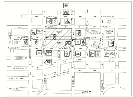
Construction: The Duval County Unified Courthouse Facility (DCUCF) is located near the heart of Jacksonville, Florida at the intersection of Clay Street and Monroe Street. The construction of this structure will take place over a 798,000 square foot desolate strip of land to help display architectural style and diligence to the Duval County area. An obstacle that this project faces is maintaining a maximum productivity site logistics plan in a high volume community environment. To sustain work efforts and community atmosphere, a plan was devised to reroute transition roads that led to the main stream roads of Clay Street and Monroe Street (Figure 1). This plan helped ease congestion within the project work area boundaries and allowed for effective transportation of site products and services. Project sequencing is broken-up into four sectional areas that include center, colonnade, west and east respectively. The midpoint of the structure is first constructed then expands to the west and east components. After the basic structure is made, the interior work sequence starts on the outer limits and proceeds to the center portion to conclude with the colonnade section. Each section starts as the preceding section has the basic divisions finalized so multiple portions can be constructed at one time. The DCUCF is awarded with the rating of LEED Certification. Efforts of sustainability are reached through recycled content of materials, regional materials, certified wood, low-emitting materials, site disturbance, construction waste management, and construction indoor air quality management. Recycling of material in the office and outside the office was urged to help promote “green” awareness. The office recycles aluminum and plastics and uses “green” cleaning products to aid in the environment. The field keeps track of steel and cardboard recycling divisions with the subcontractors. At one point wood recycling units were dispersed throughout the site until the recycler business loss occurred, and no other wood recycling businesses could be located within a 500 mile radius. Adhesive control limits ranged with VOC contents of 30 g/L to 775g/L that were within target of LEED requirements. Figure 1. Detour Site Logistics Plan
|
|
Electrical: The electrical distribution system is powered by four utility transformers valuing at 2500kVA. A back-up generator was supplied and contributed a 3-phase 277/480V with 1875kVA. All electrical services for the Duval County Unified Courthouse Facility were provided by J.E.A. utility company.
|
|
Lighting: Interior lighting is composed of T5, T8, and Compact fluorescent fixtures along with HID fixtures to maintain work productivity related to specific tasks. Exterior lighting is supported by metal halide fixtures to accommodate for display and security lighting. Energy efficient control is established by timed switches and motion sensors within the interior boundaries. Main lighting fixture uses can be referenced in Figure 2.
|
|
Mechanical: The main mechanical room is located on the first floor that houses a fire pump, domestic water boost pump, boiler, and compressor. A separate shed room consists of two chiller pumps from outside the building. The first through sixth floor contain an additional mechanical room for individual floor support distribution. The seventh floor receives energy from the sixth floor mechanical system. The overall mechanical component is a Variable Air Volume system supported by twenty-five air handling units valuing between 3300 to 50000 CFM. A recovering system was installed with three make-up air handling units at 40000 CFM. Pump channels are referenced to chilled water, CRU, and MAU divisions that connect to the exterior water main lines. Two boilers with low emission ratings and input/output levels of 16330/13390 CFM are implemented in the DCUCF through the J.E.A. Public Utility Company. Plumbing exponents are configured to gravity and pressure flow rates to meet the 3139 F.U. and 695 GPM requirements for sewage flow and water demand of the building. To meet these expected values of sewage flow, a minimum 3-8” lines will be manufactured. For water demand 8” domestic lines must be installed. These systems are tailored from a Triplex System Booster Pump with iron, steel, and copper piping units. Roof water distribution consists of downspout nozzles and insulated condensate drains.
|
|
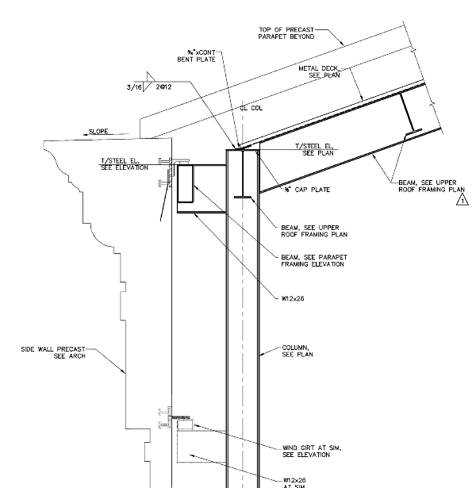
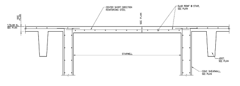
Structural: The building foundation system is constructed with auger and lateral piles at 125, 56, and 12 tons per pile with pile caps at 42” to 75” in depth. The foundation slab and floor slabs are poured and finished at 5” with 3,000psi concrete. These slabs contain 2-#4 x 3’-0” LG re-entrant bars that are centered at each re-entrant corner. Crack control, typical construction, and expansion joints at walls are best implemented with joints sealants and 1/8” sawcuts. Concrete footings vary with dimensions of 5’-6” x 3’-2”, 4’-0” x 3’-2”, 3’-0” x 3’-2”, and 2’-0” x 3’-0” valuing at 3,000psi concrete strength, dependent on loadbearing calculations. The superstructure is mainly composed of W 8x29, W 19x29, W 27x29, and W 36x29 steel beams and joists. These beams and joists are constructed with 4,000psi concrete strength and follow a symmetrical pattern that are erected within the given parameters of four sections. A lateral bracing system is used to best resist in calculated live and dead loads. Concrete columns range from 16”x24” to 24”x28” with 10 to 20 bar at 50ksi. Sixteen shear walls exist within the structure and are designed for 4,000psi which withhold loading on elevator shafts and stairwells. Load bearing walls shall be constructed with Type II hollow concrete masonry units with ASTM C270, Type “S” mortar. This wall system is composed of masonry control joints, two vertical wall joint reinforcements, dowels, and masonry bond beams. All cells are filled with vertical reinforcing solid. Concrete masonry wall connection to precast concrete beam shall use a bolt connection on a steel plate with one-inch clearing to deck above. Precast paneling is used for a nicely finished façade. The panels have a concrete strength of 5,000psi at 28 days with 3/8” diameter reinforcing. The steep roofing system is supported by steel beams of W 16x31, W18x40, and W 18x50. These beams help transfer loads from the metal roof back down to the ground using chevron and lateral bracing efforts. The assembly of a steep roof can be referenced in Figure 3. A flat roofing system is displayed on the west and east sections of the building (Figure 4). This system is made up of limestone aggregate concrete at 4,000psi with 1-1/2 “ deep metal decking and sloped pits for water drainage. Figure 3. Steep Roof System Connection
|
|
Figure 4. Flat Roof System Connection |
|
Fire Protection: The large capacity of building size allots for a combination of standpipes with wet and dry pipe systems connected to the building’s fire alarm system. 4” diameter piping connects from the bottom floor and distributes the water flow system all the way to the roof schematic where the sprinkler main is located. Water origination comes from a fire pump that regulates 1000 GPM with a 145 pressure boost. A secondary jockey pump regulates 10 GPM and a 155 pressure boost provided by Aurora manufacturing company. Fire suppression methods are achieved through smoke and fire dampers divided into three-five zones per floor averaging at 40,000 square feet. These systems are roof and wall mounted to maximize fire and smoke occupant awareness.
|
|
Telecommunication: All telecommunication wiring is supported by tubular runways, ladder racks, “J”-hooks, and ground bus bars. These products make easy connections to disperse wiring from floor-to-floor and room-to-room to meet the wall and floor outlets and flush boxes. A minimum of 100 foot of slack of cable is needed for each hand-hole along with thirty feet of slack at each termination point. 4” PVC SCHED 40 conduit is used in relation to 1” inner-duct to relay wiring from the building to the existing exterior voice-data lines. Audio visual is used in the form of overhead projectors, flat panel display, audio/video camera, and ceiling mounted document cameras. These systems are best represented in the courtroom proceedings and office spaces where security and public domain is located.
|
|
Transportation: Transportation revolves around fifteen elevator units, fourteen stairwells, and two escalators. The elevator units are broken up into public purpose functions (located at the front of building) and private authorization purpose functions (located in rear of the building). These divisions allow for administrative personnel to have direct access to their quarters and easy movability to accomplish work without public interference and security issues. Stairwells permit for ease of congestion and for fire evacuation requirements. Escalators are presented at the front of the building for grand aesthetic purposes for transportation.
|

|
Figure 2. Fixture Type Relationships |
|
|
Room/Task |
Fixture Type |
|
Courtrooms |
Fluorescent/HID/Emergency/Recessed |
|
Administrative Affairs |
Fluorescent/Emergency/Pendant |
|
Corridors |
Fluorescent/Emergency/Pendant |
|
Attorney Affairs |
Fluorescent/Emergency/Recessed |
|
Judicial Affairs |
Fluorescent/Emergency/Recessed |
|
Custodian Affairs |
Fluorescent/Emergency/Pendant |