
| ASSIGMENTS | FINAL REPORT | PRESENTATION | REFLECTIONS |
Existing Conditions/Architecture
The building will serve the community as a playhouse, office support space, as well as university office space. The site rests in a community with a rich historical brick building encroaching all around. To restore the historical features of the building the entrance doors, entrance canopy, masonry facade, signage, and lighting at the playhouse special measures are taken.
The existing four story 33,000SF building consists of four separate townhouses that were merged together during the 1940’s. The building has historical and cultural significance in that it houses a 4,400SF playhouse on the ground and basement levels which is scheduled to remain. As part of the project, the interior of the theater will be demolished and rebuilt. The playhouse portion of the building is located at the southern end of the site’s 8,430 SF footprint. Four walls of the original theatre which is located on the basement and ground floor level will remain throughout construction.
These four walls mortared together with various stone and brick will be temporarily preserved by shoring the walls with steel beam structural system. This is a very challenging task because there is a dentist office on the south side. In addition there are restaurants adjacent to the building which lends to daily delivery. Also there are apartments on the north and west side and a small one way street on the east side. The playhouse portion of the building is located in the southern end of the site
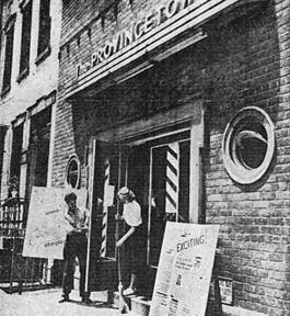
Figure 1: 1945 View of Playhouse Entrance | Courtesy of Owner
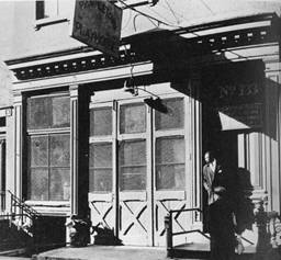
Figure 2: 1935-36 View of Playhouse Entrance | Courtesy of Owner
Demolition
The demolition of the existing building started with the removal of the hvac units from the roof. From there the Con Edison power and gas, Verizon services were cut off. Before demolition could start, an existing conditions survey of adjacent building was conducted. Through construction vibration monitoring was used. Asbestos Abatement was performed by owner. A protective sidewalk bridge was used to permit pedestrians flow during non-working hours.
The demolition of the existing 33,000SF building consists of four separate townhouses that were merged together during the 1940’s. The existing building is compiled of brick and mortar, which has been primarily demoed by excavators. While, the playhouse required hand demolition method The building has historical and cultural significance in that it houses a 4,400SF playhouse on the ground and basement levels which is scheduled to remain. As part of the project, the interior of the theater will be demolished and rebuilt. The playhouse portion of the building is located at the southern end of the site’s 8,430 SF footprint. Four walls of the original theatre which is located on the basement and ground floor level will remain throughout construction.
These four walls mortared together with various stone and brick will be temporarily preserved by shoring the walls with steel beam structural system. This is a very challenging task because there is a dentist office on the south side. In addition there are restaurants adjacent to the building which lends to daily delivery. Also there are apartments on the north and west side and a small one way street on the east side. The playhouse portion of the building is located in the southern end of the site.
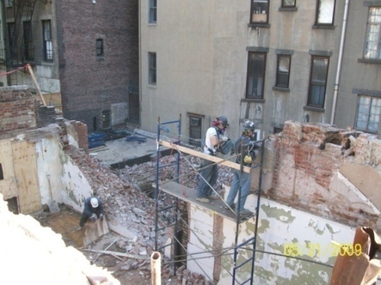
Figure 3: Shows Hand Demolition Techniques being Utilized | Provided by Skanska
Support of Excavation
The site resides in an Metropolitan area. There are no streams or natural water courses visible on premises. Neither are there any vaults located below the sidewalk level. The premise does not lie within any flood hazard area designated by the federal emergency management agency. The site will be dug down an additional 12 feet requiring sheeting at the west side, east side, and north wall. During the excavation stage under pinning was necessary for the existing apartments which are abut to the north and west wall in order to start foundation work. Also underpinning is required at the wall of the existing playhouse which will be the common wall for the office and play house. Piles were then drilled at the east property line to strengthen and stabilize existing soil and foundations of adjacent buildings. In addition to the piles drilled sheeting was installed. Then the 16 foot high construction fence was erected. Next the reinforced mat foundation slab is poured on top of the piles. Ground water is expected at 15’ 8” therefore a dewatering system is used. De watering the pumping of water from below ground level is then utilized. Well points were installed and the dewatering system ran 24/7 for 22 weeks.
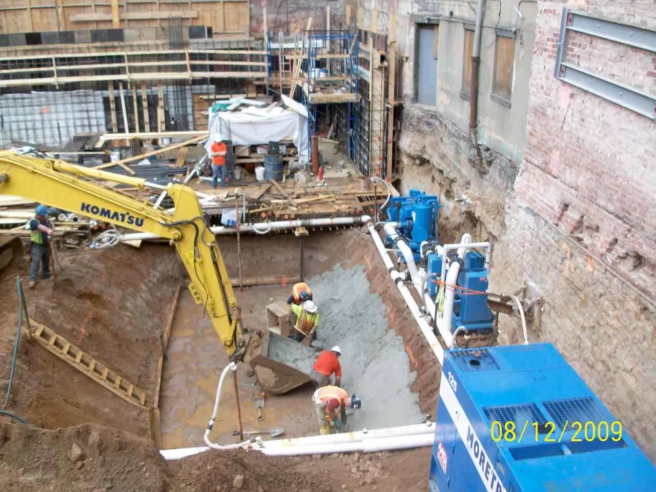
Figure 4: Displays the Dewatering System | Provided By Skanska
Foundation
The Foundation is a 30” thick matt slab on top of a 3” concrete mud slab. New 1’ 4” thick foundation walls are used to support the office portion of the building. The playhouses existing walls support the 2nd through 6th. Buttresses laterally brace the existing masonry walls of the playhouse. In addition, there are Tie beams that span the playhouse in the north and south direction within the matt slab. Underneath the playhouse’s tie beams is a new concrete footing. As addressed in the existing conditions new underpinning was added under the adjacent buildings along the north south and eastern sides of the building.
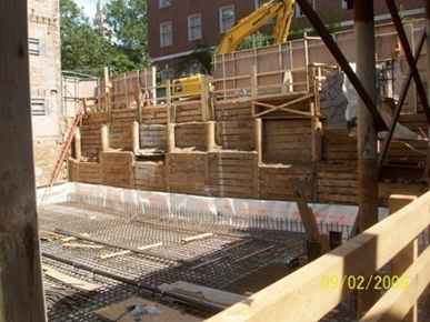
Figure 5: Shows the Sheeting (Lagging) and Piles on the East Side (Mac Dougal Street) | Provided By Skanska
Cast-in-Place Concrete
Conventional concrete two-way plate structure construction is utilized throughout the building with reinforcement specified by middle strip and column strip details. All of the concrete is 5000psi concrete. The floor construction is a 10” deep flat plate slab. The columns’ sizes range from 12”x24” to 18”x36”. The anticipated columns loads at cellar level for the new structure are about 1,000 kips (dead plus live load). The column layout is 24-feet on center. At the exterior column in the slabs stud rails by Decon are used to enhance the shear capacity of the floors along the eastern side of building. 12”x12” and 12”x13” beams are used to brace the slab along the east and west sides of the elevator. The cast-in-place concrete construction presented the construction team with many obstacles.
The concrete slabs and columns were poured at a rate of one floor per week, with a crew of 25 men. This progress was hindered by the complexities of the regulations for the new cast-in-place scissor stairs. The construction crew laid out the formwork to accommodate the conduct and water holes ahead of time before the pure, so that the penetrations did not weaken the structural integrity of the slab. One of the challenges encountered was pouring the 2st floor above the theatre. 26 feet of scaffolding was used to support the formwork and concrete; this logistical nightmare was intensified due to the steel structural bracing as shown in the Figure 6. Simon forms were used for the vertical formwork of the foundation walls and the load bearing wall in the theatre. A pump truck was used to place the cast-in-place concrete. Power trowel were used to finish the elevated slab.
Throughout construction vibration monitoring has been used to guarantee none of the adjacent buildings are disturbed. Despite the precautions taken to preserve the walls of the playhouse, the north wall had to be removed because of it’s the structural integrity.
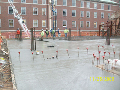
Figure 6: Pump Truck Placement Method | Provided By Skanska
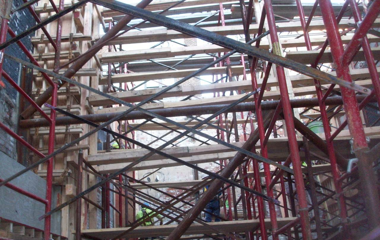
Figure 7: Shows the Addition of Shoring to the Steel Bracing | Provided By Skanska
Structural Steel Frame
A temporary steel frame was used to preserve the existing theatre walls and the adjacent building. This made construction activity very difficult due to the structural bracing. The steel bracing was anchored to the adjacent building’s masonry wall. Double l-angle steel wielded together was used for vertical members and round hollow structural sections (hss) steel tubing was used for the lateral members shown in Figures 3 and Figure 4. The existing adjacent structure required additional c-channel to reinforce the neighboring structure by tying into the floor wood trusses of the neighboring structure; because the wall was not load bearing wall it was only two courses thick. One lane of traffic was closed during construction to allow for a crawler crane to be used.
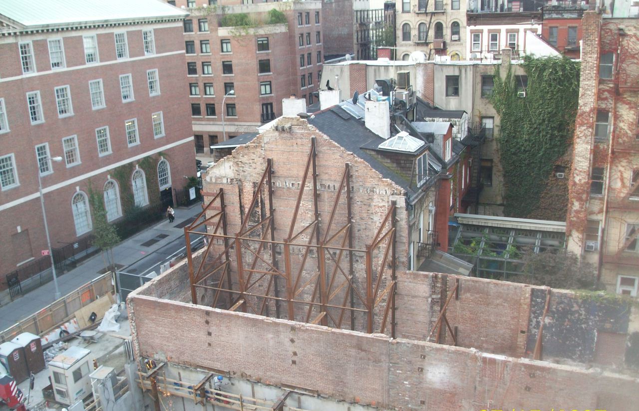
Figure 8: Shows Temporary Structural Steel Bracing | Provided By Skanska
Building Enclosure
The all natural brick facade will seamlessly blend into the neighboring buildings. Between the sixth floor and roof there is corrugated metal panel. The windows will be double hung with precast concrete sill and precast concrete lintel. The First through sixth floor features a brick facade. Because the brick facade laid in the winter temporary heat is needed for exterior masonry and building finishes. Three curtain wall slots were chosen to break up the brick façade to blend in with the surrounding townhouse buildings. The curtain wall system type of glazing is the kawneer powder coated aluminum. While, the sixth floor features two foot terracotta cornice crown.
The east and west side of the building has roof terrace set back at the second and fifth floor. On the western side the top layer has pavers on pedestals, tapered rigid insulation, 5” rigid insulation on top of the concrete slab. The eastern terrace roofing membrane is placed on exterior sheathing boards.
The Hydrotech's unique monolithic membrane 6125 is fluid applied rubberized asphalt. Monolithic Membrane 6125 EV(environmental grade), that can be formulated with up to 25% post-consumer recycled content. The primary advantages of the monolithic membrane is there are no seams to fail, the membrane is bonded directly to the substrate thus restricts lateral water movement if damaged, resistant to fertilizers and other mild acids, no VOC restrictions; contains no PVCs, and most importantly the membrane is installed only by authorized and trained applicators.
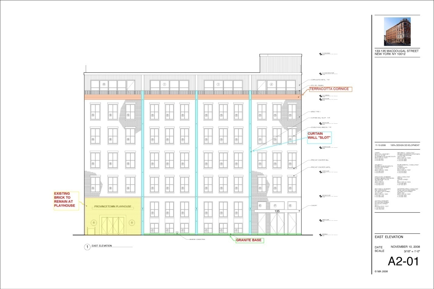
Figure 9: Shows the Three Curtain Walls Slots, Granite Base, Existing Wall to remain, and the Terracotta Cornice | Provided By Skanska
Curtain Wall
Three curtain wall slots were chosen to break up the brick façade to blend in with the surrounding townhouse buildings. The curtain wall system type of glazing is the Kawneer powder coated aluminum. This curtain wall configuration is dry glazed gaskets. The glass features fire rated ¾” 2 ply glass. There is 2 Layers of ½” fire rated gypsum board separating the curtain wall frame and metal stud which is mounted with a powder actuator fastener.
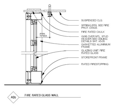
Figure 10: Shows a Typical Curtain Wall Connection | Provided By Owner
Masonry/ Precast Lintels
The all natural brick veneer is non-bearing will seamlessly blend into the neighboring buildings. The 4” brick veneer is a running bond. Windows will be double hung with 4”x8”x4’-4” precast concrete lintels and 4”x4”x4’ window sill lintels to accent the windows. Concrete lintels and the brick veneer are attached with a steel L-angle that is fastened to the 8” concrete masonry units. The expansion bolts anchor the angles. Cmu that have anchors going into mortar joint between them are grouted. The base of the building features a 70sf granite base at Mac Dougal Street. First through sixth floor features a brick facade. While, the sixth floor features 18” foot high terracotta cornice crown. Because the brick facade was laid in the winter temporary heat is needed for exterior masonry and building finishes. Swing scaffolding is used along the north, south, and east perimeter; while steel tubular masonry scaffolding is used for the west perimeter.
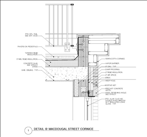
Figure 11:Shows the Lintel Connection to the 8” CMU | Provided By Owner
Mechanical System
The primary hvac system is constant air volume with vav boxes to regulate the temperature within the office building. Sound lining is installed in all of the ductwork. There are two air handling units in the theater both are 8650CFM located on the basement floor. Also, electric cabinet heaters are provided in the vestibule of the theatre and the office building in order to supplement for the excess of loads contributed by the entrance doors on the first floor. The basement of the office building is 4700CFM. The first floor has two 6000CFM air handling units. The office building air handling units are 6300cfm on the second to the fifth floor. The University’s central plant will provide chilled water and hot water for cooling and heating via new underground source piping. The on campus Cogeneration Plant will allow for future utility tie-in. The hot water will come from this neighbor building through an underground tunnel; this caused the street separating the two buildings to be closed while the tunnel was excavated.
This building is unique in that the heat exchanger and the water pumps are located across the street. The heat exchanger is located on the cellar floor is 200GPM on the primary side and 40GPM on the secondary side. The hot water is supplied by a 200GPM pump and the chilled water is supplied with a 360GPM pump. These pumps are equipped with variable frequency drives. Electric unit heaters are provided in the mechanical and electrical rooms. Hydronic fin tub baseboard radiation is provided behind the windows of the building to compensate for the additional infiltration loads. This building is unique in that the heat exchanger and the water pumps are located across the street. Hence the coordination was very difficult.
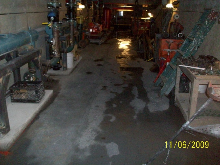
Figure 12: Illustrates the Heat Exchanger in the Neighboring Building | Provided by the Skanska
Electrical System
The existing play house service has been completely removed. The new service includes both the theatre and the office building. Two new 5KV Con Edison service is split at the basement entrance. This then passes through a ventilated dry type transformer which converts the voltage from 4160V to 120/208V. One of the service passes through 3 sets of 4#5000MCM, 1#1/0GND in (3) 3-1/2”C to the theatre. Alternatively, the office building’s service is (8) sets of 4 #500MCM 1#1/0GND in (3) 3-1/2” C passes through a 2500A service switch then into the office building’s switchboard No.1 1200A 120/208V, 3 phase 4 wire 60Hz. Each of the floors of the building is equipped with a lighting panel and receptacle panel. This allowed for easier coordination between the trades because only one 4 #500MCM-1#1/OGND-3-1/2”C feeder is supplied for each set of panel boards between floors.
Fire Protection
The main supply for the sprinkler system is a 6” pipe, which will be connected to an existing supply. In addition, there is a 3” x 3” x 4” Siamese connection for the sprinkler system. Each floor is equipped with a new floor control valve assembly. Also the building has a water flow detector on each floor. In the Lobby and corridor areas there are concealed sprinkler head with quick response. Open areas with no ceilings, closets, and steam/boiler rooms have upright sprinkler. Soffit areas and perimeter offices have a quick response head extended coverage with horizontal sidewall in order to reach a broader area.The minimum pressure at each sprinkler head is 7 psi. The design criterion is a wet pipe system. The light hazard office areas were designed for 0.10 gpm/sq.ft. The light hazard areas are designed for a maximum coverage per sprinkler head of 225 sq. ft. The ordinary hazard storage areas were designed for 0.16 gpm/sq.ft. Ordinary hazard areas are designed for a 225 sq.ft. maximum coverage per sprinkler head. Fire protection is supplied by a 400gpm 20hp electric fire pump and a jockey pump which is 9gpm 3/4hp.
Theatre Lighting
In addition to the stage lighting there are metal halide fixtures and incandescent downlighting are used. Lobby/Gallery uses metal halide downlighting. The Rehearsal space utilizes 2’ x 2’ fluorescent downlighting.
Office Building Lighting
Six foot wall mounted linearfluorescent light fixtures are used in the individual offices. Surfaced mounted fluorescent down lights are used at the main entrance of the office building. Incandescentexterior lights are used on the roof terrace of the green roof terrace on the second floor. Wall mounted uplightingis used in the cellar level office suites. Pendant ceiling mounted light fixtures are used to light the conference rooms. Linear ceiling mounted fluorescent fixtures are used in the restrooms. Offices on the sixth floor are lite with pendant mounted fluorescent indirect/direct fixtures. Compact fluorescent light fixtures are used to light the corridors. The west side roof features two 5’x14’ sky lights which will be used to day light the office suite below.
Lighting Controls
All lighting circuits terminate at the panel with a built-in time clock. All lighting is controlled via wall mounted occupancy sensors. For open area a time clock with extended time override via smart circuit breaker is used.
Telecommunication and Data
The office building provides a complete intercom system from the front entrance to all floors. The telecom system is feed by (2) 4” empty conduit for telecom/data from underground from across the street. The main tele/data riser throughout the levels of the office building is (2) 4” E.C. conduit.
Security
All of the restrooms contain a panic button. Both the main entrances of the theatre and the office building has a card reader and door contact. The main entrance of the office building and theatre is accompanied by a video intercom. Once, entering the office building there are two video surveillance cameras, also there’s video cameras at the elevator entrances. At the northwest corner of the building there is a audio visual annunciator. At the Basement level there are ceiling mounted glass break sensors. Within the office building there is a card reader for access to the mechanical rooms and telecom rooms. The east side of the building features 2 window contacts at each window one at the top and one at the bottom.
Audio and Video Theatre
The theatre contains communication single channel wall station in the corridorat the cellar level. Also there is a communication 2 channel wall boxin the lobby connected to the box office. The theatre also contains four sound panels one in each corner of the stage that entails eight microphone (4 return to the sound booth and two A/B communication outlets. In front of the stage lies a sound/AV floor bock for audio connections e.g. (microphone, line, and return), internet, local Ethernet. There are also a total of five speakers above the seating which are wired to the house technician’s position and control booth. In addition, there is a speaker in the lobby on the basement floor and speaker in the rehearsal and dressing rooms. The technician’s table is located in the center of the theatre above the seating on the theatre’s mezzanine. The technician’s table is wired with 2 local Ethernet for internet, communication channel A & B connection 40 channel snake.
Sustainability
The Owner requires the Contractor to implement practices and procedures to meet the project’s environmental performance goals, which include achieving LEED Silver Certification. Specific project goals that may impact this area of work include: use of recycled-content materials; use of locally-manufactured materials; use of low-emitting materials; construction waste recycling; and the implementation of a construction indoor air quality management plan. The west side roof features two 5’x14’ sky lights which will be used to day light the office suite below.
The Green roof not only adds aesthetic appeal to the building and reduces the amount of rain water runoff. The green roof is a 12” Intensive American Hydotech Lite Top. This type of roofing system was chosen to accommodate plants, shrubs, and trees. There are three sets of green roofs the second floor, the sixth floor, and roof.
The design and construction team has worked with Kinetix LEED AP team members to ensure that every sustainable alternative was addressed from start to finish. This pursuit of sustainable building was lead by the client’s active role. The client recently completed a cogeneration plant which will provide heat and power to the site throughout the year. The owner also utilizes a wind power contract.
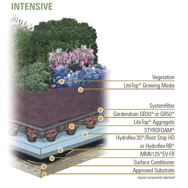
Figure 13: Green Roof Section | Courtesy of Hydrotech
Elevator (Vertical Transportation)
There are three elevators utilized for vertical transportation of the building. The office’selevators operate from the cellar level to the roof which is a total of 8 stops. There are two office elevators one is used only for passengers and the other is used for passenger/freight. The theatre’sholeless hydraulic elevator operates from the cellar level to the basement level which is a total of 2 stops. The other type of vertical transportation is a handicap lift at the office building lobby. This is required because there is a 4’-4” elevation change from the sidewalk level to the basement level.
Construction
The contract type is construction management at risk with negotiation. The construction manager Skanska was brought in at the inception of the project to give its construction knowledge to the owner. For one, the project is a fast track, so all of the construction details were not, so a guaranteed maximum price was not suitable. Skanska has worked with the client on many past projects; therefore there was a high level of trust between Skanska and the building owner. Skanska is managing the project with an open book policy. Skanska has competitively bid all work on a lump sum basis with the building trades.
One of the lanes on a two way street has been closed during the construction to allow for deliveries to be made on a daily basis.Throughout the duration of the construction a crawler crane was used extensively. This crawler crane was placed on the closed traffic lane. The crawler crane was used from the start of construction until the interior finishes activities started. This required a construction barricade to be constructed to allow for construction deliveries and a path for the crane to move. During nonworking hours a pedestrian walk with overhead protection passed in between the barricade and the building footprint.
A major obstacle for an inner city project is obtaining all the major building permits. The building permits that were required prior to the start of construction were very expensive and time consuming. For the substructure alone, dewatering, substructure, underpinning, sheeting and shoring permits were required. In addition, permits were required for all major building trades.
Subguard is utilized for subcontractor bonds. This type of bonding is far superior to the traditional performance and payment bonds for the experienced construction manager. Subguard brings cost savings to the construction manager. Subguard is initiated at the onset of sub contractor default; unlike traditional bonds which can take months to come into effect. This puts the Skanska in the position to enact a remedy for the problem and Subguard pays the costs. The construction manager takes on higher risks including: rental agreements, bodily injury claims, and purchase orders. Therefore, Skanska implements extensive procurement and purchasing prequalification. In addition, Skanska implements its Injury Free Environment program to ensure the New York and OSHA safety rules are withheld.
Building Statistics Part 1 |
||
General Building Data |
||
| Building name | Project X | |
| Client | Any town University | |
| Location | New York, NY | |
| Function | Office building and Theatre | |
| Dates of Construction | August 2008- July 2010 | |
| Construction Cost | Withheld at owners request | |
| Project Delivery | Fast Track, Construction Management | |
| Lot Size | 96'-6" x 88'-9" | |
| Lot Area | 8432 SF | |
| Width of Street | 50' (narrow street) | |
| Construction Classification | I-C Non-Combustible 2 HR. Protection | |
| Occupancy Group | E Business (27-253) | |
| General Codes | New York Building Code Article 19 | |
| Earthquake Codes | Local Law 17/95 of NY | |
| Flood Zone Code | Local Law 58/83 of NY | |
| Disabilities Codes | Local Law 58/87 of NY | |
| Concrete Code | ACI 318 | |
| Construciton Classification (Table 3-4) | I-C Non-combustible 2 hr. Protection | |
| Area & Height Limitations (Table 4-2 for Sprinklered buildings): | All Partitions separating use groups to be min 2 hr. Per Table 5-1 & 5-2 | |
| For Business E | Max. Travel Dist. (Sprinklered)=300' | |
| Corridors min. width=44" | ||
| Max. dead end corridors=50' | ||
| Exit & Access Requirements: | Occupant load (table 6-2) | |
| Zoning | Residential Use: R7-2 Commercial Use:C1-5 | |
| Height & Setback | Maximum Height 60’ or 6 Stories | |
| Historical Requirements | The original four walls of the Playhouse is to remain up to the second floor | |
Building SF |
||
| Floor | Existing Gross FA | Proposed Gross FA |
| Cellar | 4,580 SQ FT | 8,430 SQ FT |
| Basement | 7,620 SQ FT | 8,430 SQ FT |
| Floor 1 | 6,410 SQ FT | 8,430 SQ FT |
| Floor 2 | 5,390 SQ FT | 6,256 SQ FT |
| Floor 3 | 4,480 SQ FT | 6,256 SQ FT |
| Floor 4 | 4,480 SQ FT | 6,256 SQ FT |
| Floor 5 | 0 SQ FT | 6,256 SQ FT |
| Floor 6 | 0 SQ FT | 4,326 SQ FT |
| Total Area | 39,960 SQ FT | 54,640 SQ FT |
Project Team |
||
| CM | Skanska | www.skanska.com |
| Historical Consultant | Higgins Quasebarth & Partners | http://www.hqpreservation.com/ |
| Architect | Morris Adjmi Architects | http://www.ma.com/ |
| Environmental Consultants | Langan | http://home.langan.com/web/ |
| Structural Engineer | Robert Silman Associates | http://www.rsapc.com/ |
| LEED Consultant | Kinetix | http://www.kinetixllc.com/ |
| Mechanical Engineer | FMC Associates | http://www.fmcassociates.com/ |
| Waterproofing Consultants | Frank Seta & Associates | http://www.frankseta.com/ |
| Lighting Designer | RS Lighting Design | http://www.rsltg.com/ |
Contact: lag290@psu.edu
User Note:The Capstone Project Electronic Portfolio (CPEP) is a web-based project and information center. It contains material produced for a year-long Senior Thesis class. Its purpose, in addition to providing central storage of individual assignments, is to foster communication and collaboration between student, faculty consultant, course instructors, and industry consultants. This website is dedicated to the research and analysis conducted via guidelines provided by the Department of Architectural Engineering. For an explanation of this capstone design course and its requirements. The Capstone Project Electronic Portfolio (CPEP) is a web‐based project and information center. General description: It contains material produced for a year‐long Senior Thesis class. Its purpose, in addition to providing central storage of individual assignments, is to foster communication and collaboration between student, faculty consultant, course instructors, and industry consultants. This website is dedicated to the research and analysis conducted via guidelines provided by the Department of Architectural Engineering. For an explanation of this capstone design course and its requirements click here. |