|
All images are provided courtesy of The Pennsylvania State University, unless otherwise noted. General Description: The Capstone Project Electronic Portfolio (CPEP) is a web-based project and information center. It contains material produced for a year-long Senior Thesis class. Its purpose, in addition to providing central storage of individual assignments, is to foster communication and collaboration between student, faculty consultant, course instructors, and industry consultants. This website is dedicated to the research and analysis conducted via guidelines provided by the Department of Architectural Engineering. For an explanation of this capstone design course and its requirements click here. User Note: Note: While great efforts have been taken to provide accurate and complete information on the pages of CPEP, please be aware that the information contained herewith is considered a work-in-progress for this thesis project. Modifications and changes related to the original building designs and construction methodologies for this senior thesis project are solely the interpretation of Mohammad Alhusaini. Changes and discrepancies in no way imply that the original design contained errors or was flawed. Differing assumptions, code references, requirements, and methodologies have been incorporated into this thesis project; therefore, investigation results may vary from the original design. This page was last updated on 9/2/2010, by Mohammad Alhusaini and is hosted by the AE Department ©2010 |
|
Zoning: University Planned District 5; Core of campus with highest permitted density of 1.0 FAR. As the building is in Special Zone 1, the maximum height for buildings in this zone is 65ft at the setback line, and 75ft at a point 6ft behind the setback line. Tubular Allowable Height: 160ft Actual Height of Addition: 60ft
Codes Used: PENNSYLVANIA STATE DEPARTMENT OF LABOR AND INDUSTRY 2006 INTERNATIONAL BUILDING CODE(IBC) 2006 INTERNATIONAL EXISTING BUILDING CODE(IEBC) 2006 INTERNATIONAL FIRE CODE(IFC) 2006 INTERNATIONAL MECHANICAL CODE(IMC) 2006 INTERNATIONAL PLUMBING CODE(IPC) 2006 INTERNATIONAL CODE COUNCIL ELECTRICAL DODE(ICCEC) 2003 AMERICAN NATIONAL STANDARD (ANSI A117.1-2003)
Historical requirements of building: N/A
Building Enclosure
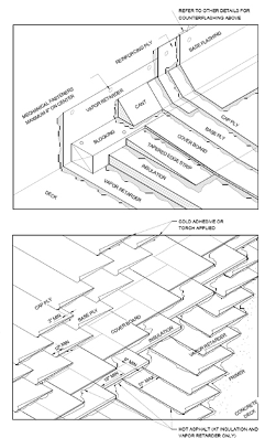
Roof The roof itself is very typical in construction; it consists of concrete deck covered in primer, then a vapor retarder in sheets, followed by insulation also in overlaying sheets, coverboard, then base ply and cap ply to top it off. The inner edges add to this assembly a cant, blocking, flashing (Lead flashing) and a reinforcing ply (refer to Figure 1).
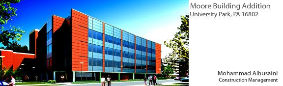
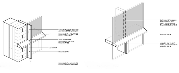
Façade The enclosure of the building includes mullions that hold veneer glass in place, and a façade that has a notable amount of glass (see render). The mullions extend from the second floor up to the top of the fourth floor and roof. This is covered by bricks for aesthetic purposes and to match Penn State’s architectural guidelines. The ground level is surrounded by an aluminum curtain-wall system. The ground itself is of a stone base for aesthetic reasons. The windows include roller shades and between the windows is an assembly of aluminum curtain-wall for aesthetic purposes. The columns are also covered to match the aluminum theme throughout the façade. The glazing itself has not yet been specified, but sizes are all mentioned. The same is the case for the shades (i.e. double v single shades throughout the building.) The walls of the façade also include brick wall assembly with recessed brick coursing that will complement with look of aluminum and brick around the rest of the building (refer to Figure 2).
|
|
Figure 1 |
|
Figure 2 |
|
Sustainability Features |
|
Structural System The first floor of the building has a structural system different to the rest of the building, with the west side consisting of the steel structure and the north and east sides of the building consisting of steel beams that hold the rest of the structure up as this section is open and not enclosed. The center section consists of concrete cast-in-place walls. The rest of the floors (3 thru’ 4) all have wide flange beams to support them. These beams range in size from W10X12 to W21X44 with the primary beam sizes being W16X26-40 for the interior part of the building, whilst the exterior walls are primarily W21X44. The roof is split into the “Low Roof” and “High Roof” with both consisting of relatively smaller beam sizes for support. Some of which are W10X12. The columns in the building are primarily W10X33 to W12X72. The structure is made up of a braced frame system which connects to the rest of the building structure through the W21X44 Beams. This braced frame system runs parallel from North to South along the entire structure. All decks are composite decks and the concrete strength is 4000psi. The foundation consists of a strip footing assembly that is surrounding the west section of the building, and connects to the original building at the strip footing. The footings of the new building are spaced about ~10’ O.C. for most of them with several exceptions. The sizes of the spread footings range from 5’X5’ to 10’X15’ and are from 12” to 33” thick. The encasements of the columns are concrete 30”x30” on top of the footing. The slab-on-grade concrete strength is 4000psi as well as the footings and the piers used in the building. The building is in category “D” for seismic loads, with an importance factor of 1.25. The floor to floor height is 12’-6” for all floors.
Mechanical In the basement level of the Moore building are chilled/hot water pumps along with the secondary chilled water pumps, all raised 4” on a concrete pad of their own. Two of the Chilled Water Pumps produce a flow of 905GPM, whilst the last produces a flow of 130GPM. The secondary chilled water pumps’ flow is rated at 245GPM and the hot water pumps’ flow is rated at 500GPM. There also exists a condensate pressure pump as well as several unit heaters. The Hot water supply and return pipes are capped for future phase II. They are located in the basement as well. There are two main air handling units. The first is supplying a chilled beam system (19,000CFM AHU 29.85BHP @ 1800RPM) whilst the other is supplying the VAVs in the building (31,000CFM AHU 48.80BHP @ 1800RPM). The building consists of both variable and constant air volume systems. The new AHUs are located in the basement level of the new building. There is an existing AHU in the penthouse of the existing structure as well.
Lighting With 48 different fixture types in the Moore Building Addition, there is definitely variety. The vast majority of the fixtures use a 277V source with only a few using 120V to power them. This is true mostly due to the fact that the most predominantly used fixture is a 55 Watt T8 luminaire (code FT58). These are used in, but not limited to, the labs, classrooms, offices, and therapy and breakout rooms. The rest of the luminaires are used for aesthetic purposes and in some ambient lighting situations.
Electrical System The electrical system is quite sophisticated in Moore Building Addition. The main equipment panel board has a distribution of 3 Phase 480V. The demand on this panel board is 336KVa. Most if the rest of the panel boards are 480Y/277V 3 Phase wiring with some 240Y/120V three and single phase wiring. Electrical connection is made in manhole #201. Also at manhole #201 is an emergency connection rated at 4160V. A 1000KVA transformer is used with 12.47KV Primary and 480/277V Secondary coils which provides power to the building and is provided by Office of Physical Plant. Main Switchgear has a rating of 42,000 AIC. Also, there are both a standby service voltage switch and standby distribution panels for the addition.
Fire Alarm/Security and Fire Protection The fire protection in the Moore Building Addition is made up of visual and audible indicators and speakers, respectively. Two emergency call boxes exist on the premises (4th and 5th floors) and they route the distress signal to PSU Telecom Systems. There is a fire alarm control panel is located in the basement. There is also a Duress Push Button to warn university police of emergencies. The fire protection code being followed for this project is NFPA 13. All the spaces in the building are provided with automatic sprinkler protection specific to office spaces. This is with the exception of mechanical rooms etc., which are provided with their specific sprinkler requirements.
Transportation Due to the size of the building, there are two elevators that run side-by-side. They are located in a designated elevator lobby area near the atrium of the building. They are roughly in center of the southern part of the building. The elevator machine room is located in the basement and the elevators run all the way up to the fourth floor.
|
|
Figure 2 |
|
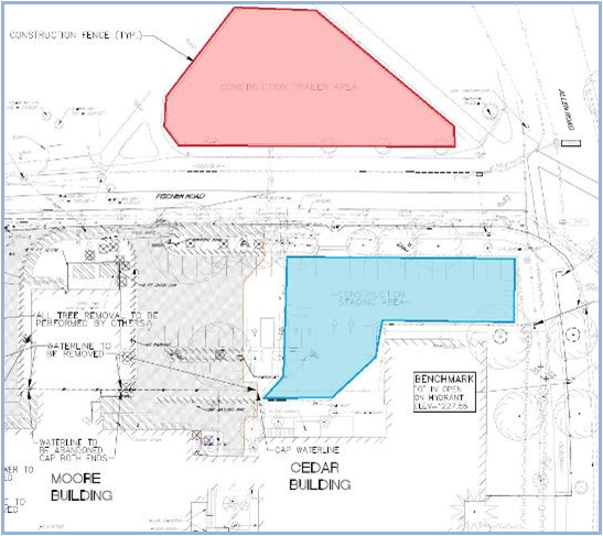
Building Statistics PART II Construction Moore Building addition is an addition to the department of psychology’s existing Moore building. It is located on the intersection of Fischer Road and Allen Road on the university campus of The Pennsylvania State University. It is located on the Northeast side of campus, with relatively less student traffic than the center of campus. This will make logistics access much easier. This is also in-part due to the fact that the building is close to Park Avenue, which is connected to the highway and where some material may find itself coming through. Although the site area is a bit tight, this will be coordinated with OPP (physical plant) for times with less dense student traffic (i.e. early morning). The construction trailers will be located across the [relatively small] road and will house all trailers (shown in RED in figure 3). The construction staging area (laydown area shown in BLUE in figure 3) will be in front of the Cedar Building, which is connected to the existing Moore building. This phase of construction (phase 1) is the addition phase of the project. The demolition requirements of this project include some removal and demolition of asphalt, concrete, trees and some curbs, which existed from the parking lot and walkways of the original building. Construction includes building classrooms, labs as well as therapy rooms; quality is of the essence . |
|
Building Statistics PART I |
|
|
Building Name |
Moore Building Addition |
|
Building Location |
University Park, PA 16802 |
|
Occupancy or Function Classification |
Department Of Psychology B (BUSINESS) |
|
Building Size |
57,000 Sq. ft |
|
Stories / Levels |
4 Stories above grade + Basement |
|
Project Leader (OPP) |
Chad Spackman |
|
A/E Firm |
|
|
C.M. Firm |
|
|
Project Start/Finish |
06/2010—01/2012 |
|
Building Cost |
$26.1 Million |
|
Project Delivery Method |
Design-Bid-Build |