|
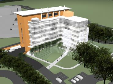
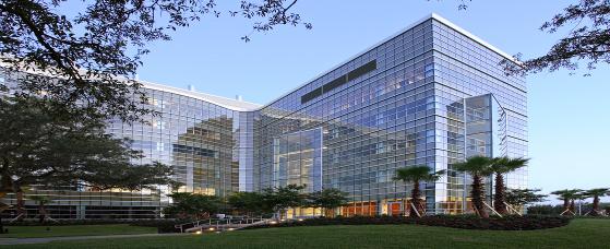
The Johnnie B. Byrd Alzheimer’s Center & Research Institute stands out with its architectural features comparing its surrounding both in design and function. The uniqueness of the building comes from the following elements: Major national model codes
2001 Florida Building Code with 2003 Updates: 2001 Florida Building Mechanical Code Florida Fire Prevention Code: 2000 National Fire Protection Association 1999 National Electrical Code (NFPA No. 70) Zoning
The building is not under the USF design process fully however it follows part of the University of South Florida planning.
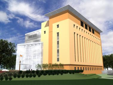
No Historical requirements of building or zone where built Building envelope The façade of the building is mainly divided into two parts. The east side consist of curtain wall glazing and Aluminum panels. The curtain wall glazing consists of: Clear Tempered, insulating laminated spandrel glass, clear insulating laminated glass, insulated fritted glass 30% silkscreen coverage pattern, insulating fritted glass 50% silkscreen coverage pattern, sunscreens and louvers (see figure 4). The west side consists of cement plaster with the same curtain wall like glazing and decorative grille with louver at the top. (see figure 5). As for the roof the use of Thermoplastic Membrane roofing was chosen with ¼”/ft slope with Aluminum parapet for architectural reasons . A 2” thick polyurethane foam coated in acrylic elastomeric emulsion coating is used as insulation. Sustainability The use of louvers, sunscreens and 30% and 50% silkscreen coverage pattern glazing were used to reduce the amount of heating/cooling of the building on the curtain wall. Other features such as low water consumption toilets and urinals, natural day-lighting, bike racks, use of local materials and products and construction waste management was used. |
|
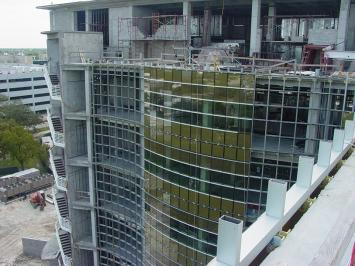
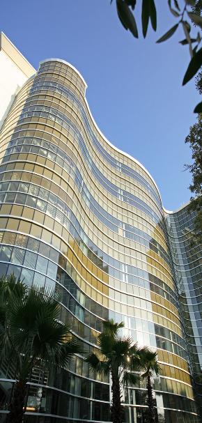
Figure 1. Wavy Curtain wall on East |

|
J.B.Byrd Alzheimer's Center |
|
Tampa, Florida |

|
Image Courtesy of HDR, Inc. |
|
Architectural Information |
|
General Data |
|
This page was last updated on 9/14/11 by Raffi Kayat and is hosted by the AE Department ©2011 |
|
Structural Information |
|
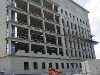
Initially, HDR Architecture Inc. structural department had designed this building as a composite system composed of steel beams, flanges, columns and a concrete slab on metal floor deck. They had their system pre-designed with specifics. The floor slab would have been consisted of a 4 1/2” of normal weight concrete on 1 ½”- 2” galvanized composite floor deck. The composite action between slabs and beams would have been achieved with welded ¾” diameter shear stud. The lateral system consisted of knee and/or chevron bracing. The roof would have been a galvanized metal roof deck supported by open web steel bar joists and beams. These were the main general ideas as more details could have been reported but seen as unimportant. However, all these ideas got tossed away when the Owner and the Contractor decided to use a more economical and efficient concrete system with precast joists. That lasts exists mainly in Florida. Hence, the use of it will be fairly new to others, which add uniqueness to this building and thesis. Floor Framing All the elevated floors of the J.B AC&RI are a hybrid system consisting of a precast joist ribs and soffit beam framing system with cast-in-place to unite the system. In fact, there are 5 main joists that have respectively the following depths: 8”, 12’, 16”, 20”, and 28”. As stated before, 5 different joist depths were used adequately depending on the required spans and uses. For the approximately 40’ span, a 20” or J4 was used spaced at 5’-8”. The area corresponding to research labs, a J3 or 16” spaced at 5-6” was used for a span of 31’. However in the same area, J4 or 20” spaced at 3’-6” and J5 or 28” at 3’-2” were used to accommodate the PET scans and MRI components respectively. Beam spacing and deck span were selected to optimize the precast joist system, to minimize structural depths, and to meet vibration control requirements.
Lateral System
Atrium Wall framing The atrium roof is approximately 60 feet above grade. Architectural trusses, approximately 36” deep are designed to support the exterior storefront glazing spanning this 60 feet. The trusses are designed to minimize deflections from hurricane force winds on this wall. The design wind speed for the area is 120mph which yields that the 50’- 60’ range was designed at 31.3 PSF. Truss components are made from structural tubes (ASTM A500, Grade B of Fy= 46Ksi) and pipes (ASTM A53,Grade B Fy= 35Ksi) in this highly visible part of the building.
Future Building Expansion Two additional project phase are anticipated using the lab core s he basis of the florr layout. However, at this time the building is not designed to accommodate he loads of the future adjacent structure.
|
|
Special Systems Information |
|
Foundations Nodarse & Associates, Inc prepared a report of Preliminary Geotechnical Exploration for this project. The subsurface exploration consisted of a Ground Penetrating Radar (GPR) survey on the site and eight Standard Penetration Test (SPT) borings to depths of 50 to 75 feet below existing site grades. For detailed result please refer to my geotechnical report that will be posted on the website.
Floor Vibration Criteria
Fire Protection |
|
Construction Information |
|
Mechanical Information |
|
Electrical / Lighting Information |
|
The General Contractor + CM were Turner Construction Company. This project was delivered to the owner by a design-bid-build method. From start to finish the construction dates were from February 7, 2006 to July 9, 2007 hence about a year and a half. The actual building cost was $23,602,477. It has been LEED silver accredited after construction. Basic construction materials of the building include stone column piers and a spread footing foundation system with below grade footing. The structure is composed of precast joist webs and soffit beam bottoms with concrete shear walls. Exterior walls are constructed of cement plaster and lath on steel stud back up framing. The curtain wall system has a kynar aluminum finish and integrates several glazing types. The entire precast joists and beam soffits are brought on site and lifted to the positions using scaffolding and then they are tied to the structure. Once the structure is erected, the formwork and the rebar reinforcing (if needed) are done then further a 5” concrete slab is casted in place to unite the system. |
|
There are two main mechanical rooms in the AC&RI, one located in the basement, and one on the seventh floor. They consist of chilled water provided by two air cooled chillers and pumps, heating water provided by two gas fired boilers and pumps, medium pressure steam provided by a gas fired boiler for use in lab equipment (sterilizers, cage wash, glass wash), one AHU serving the Atrium; fans vary air flow to maintain duct static pressure, unit is shut down when atrium smoke exhaust system is activated, two AHU’s serving office areas; fans vary air flow to maintain duct static pressure, two AHU’s serving labs; constant flow to maintain balance with exhaust systems two AHU’s (main & back-up) serving Vivarium; constant flow to maintain balance with exhaust system, a space planned for a future AHU for an imaging area (MRI, PET scan, etc.), various exhaust fans linked to various AHU’s and various miscellaneous equipment like fan coil units. |


|
Transportation Information |
|
The Alzheimer’s Center has one main bank of two public elevators located on the left side of the building that service the entire facility. Another elevator located on the left side of the building is used as a service elevator for the Labs. Staircases on both ends of the central corridor provide service from the first floor to the top of the building. |
|
The local power company installed utility transformers by TECO at level 1 on the south side of the building. The electricity enters the building through two main feeds at 30 kV. Once the electricity enters the building through the basement and into the electrical room, several transformers at 113, 75, 30 and 15 KVA respectively feed all the floors. Once the voltage levels drop down due to the transformers, to a 480/277V the feeders connect to other transformers at each floor of 75, 45 and 30 KVA which distributes the power/electricity to the various parts of the building. Three bus ducts rated for 600 A each supply power to the floor levels. Transformers are situated throughout the building to step down the voltage to the appropriate levels. Mechanical and lighting loads are fed at 480/277 V, while receptacles and other loads are at 208/120 V. Lighting fixtures predominately run at 277 V. The majority of the interior lighting is provided by a combination of linear T8's and compact fluorescents. Alternate circuits were used so that failure of one circuit would not result a blackout of an area. |
|
Location and site |
University of South Florida, Tampa Florida Fletcher Avenue |
|
|
Building Occupant Name |
University of South Florida |
|
|
Occupancy/ function |
Business Occupancy. Research Facility. |
|
|
Size (total square feet) |
108,054 sq ft, gross |
|
|
Number of stories |
7 above grade / 8 Total |
|
|
Primary project team |
|
|
|
Owner/Client: |
Johnnie B. Byrd Alzheimer’s Center & Research Institute |
|
|
Owner’s Representative: |
Ruyle, Masters, Hayes+Jennewein Architects PA |
|
|
Agency: |
USF Facilities Planning & Construction |
|
|
General Contractor + CM: |
Turner Construction Company |
|
|
Architect: |
HDR Architecture, Inc. |
|
|
Structural Engineering: |
HDR Architecture, Inc. Civil Engineering |
|
|
Mechanical & Electrical & Plumbing Engineering: |
HDR Architecture, Inc. |
|
|
Landscape Architecture: |
HDR Architecture, Inc. |
|
|
Security & Telecom: |
HDR Security Operations, Inc. |
|
|
Interior Design: |
Elements |
|
|
Dates of construction (start – finish) |
February 7, 2006 – July 9, 2007 |
|
|
Actual cost |
$23,602,477 |
|
|
Project delivery method |
Design-bid-build |
|