METRO MUSEUM OF AMERICAN ART |
LOCATION: MAJOR CITY, USA |
VINCENT A. ROSSI - CONSTRUCTION MANAGEMENT OPTION |
METRO MUSEUM OF AMERICAN ART |
LOCATION: MAJOR CITY, USA |
VINCENT A. ROSSI - CONSTRUCTION MANAGEMENT OPTION |
Building Statistics Parts I & II
BUILDING STATISTICS PART I
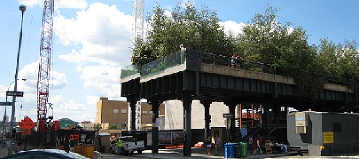
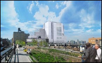
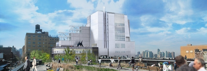
ARCHITECTURE The building site has an abandoned above ground metro line that runs from the north east corner of the site and terminates at the south east corner of the site, which is the entrance of the building. This metro line has been turned into a green walkway / park that pedestrians can use. Figure 1 shows a view from this walkway looking south onto the Metro Museum. This element of the site will be one of the main reasons for the stepped nature of the building described below. Interesting Architectural Features 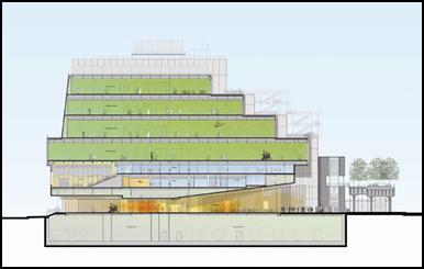 Another interesting feature of the Metro Museum is the stepped nature of the building which can be seen in Figure 2. The east side of the building, which faces the elevated metro line, steps back with each floor creating an outdoor terrace on the roofs of each level. This terrace provides the opportunity for exterior gallery space and also provides excellent views of the metro park and the city itself. Another interesting feature of the Metro Museum is the stepped nature of the building which can be seen in Figure 2. The east side of the building, which faces the elevated metro line, steps back with each floor creating an outdoor terrace on the roofs of each level. This terrace provides the opportunity for exterior gallery space and also provides excellent views of the metro park and the city itself.
Zoning & Applicable Building Codes
Note: The actual city and state names have been removed and replaced with generic titles so that the location of the building will not be made known. Historical Requirements of the District
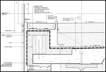
Building Roofing Multiple roofing systems make up the building enclosure. Here the primary systems will be described and discussed. First, the south roof has multiple clearstories running east to west. Around these clearstories the roofing consists of a gutter system with painted galvanized metal grating with snow melting cables where the gutter is less than five feet wide. Below the grating there is a layer of gravel followed by a composite drainage panel and waterproofing membrane. Next the north side of the roof is made up of integrally footed pre-cast concrete pavers that are backed up with ridged insulation and a composite drainage panel. Located in the middle of the north roof and surrounded by these concrete pavers is a green roofing system. This system is made up of a 4” layer of growing medium, filter fabric, drainage tray and a moisture retention mat. Below this there is a root barrier, ridged insulation, and a waterproofing membrane. Due to the stepped nature of the building a lot of the building’s roof area has been turned into terraces. These terrace roofs consist of a 4” wearing course of cast in place concrete that is backed up with ridged insulation, a composite drainage mat, and a waterproofing membrane. An example of this roof type is shown in Figure 4 below. Sustainability Features
BUILDING STATISTICS PART II Structural System The structural system uses multiple concentrically braced frames to resist the horizontal forces on the building. These braced frames are located throughout the building and consist of mainly W shaped steel members; however a few of the braced frames utilize HSS shapes as well. There is also one large truss/braced frame that runs along the entire south side of the building between the fifth and sixth floors. This location is adjacent to where the largest column free gallery in the city is located. The nine story building is framed with mainly with W shaped structural steel members that are connected with a mix of shear and moment connections. There is also horizontal bracing consisting of HSS and L shaped members within the floor framing where needed. The columns are almost all W12 or W14s with the exception of a few custom made pipe and bar columns. There are two cranes on site during the steel erection. First there is a Liebherr LR 1200 crawler crane located on the south central perimeter location of the site. Also there is a Favelle Favco tower crane whose tower ascends through the grand staircase of the museum.
Mechanical Systems The gallery and office spaces will be served by an all-air, variable air volume conditioning system. This system will consist of a total of four air conditioning units. Three of the four units are located in the cellar fan room and will each handle one third of the load for the gallery/office spaces that are located between the cellar and seventh floors. The fourth unit is located in the fan room on the ninth floor and will serve the eighth floor spaces. Supply air to, and return air from, each floor will be carried through multiple mechanical riser shafts throughout the building. The supply air that will be going to the gallery spaces will be controlled by VAV units that are located adjacent to the air conditioning systems in the cellar or ninth floor fan rooms. Once the air is transferred to its destination it is delivered to and returned from the space by traditional diffusers and grilles in the office areas; or in the case of the galleries an open ceiling plenum is used for the return air. The lobby, auditorium, and restaurant are all conditioned by similar in nature, but independent air conditioning systems. These systems are factory-assembled packaged all-air constant volume systems that are also located in the cellar fan room. The chilled water for these mechanical systems originates from three electrically driven centrifugal refrigeration machines that are sized at 300 tons-refrigeration each. These are all located in the cellar of the building and each have an individual pump that will distribute the chilled water to its end users throughout the building. The building heat originates from a hot water boiler plant also located in the cellar that includes five condensing three million BTUh hot water boilers. Pumps then circulate the hot water to the air conditioning systems or finned tube radiators.
Electrical / Lighting Systems An interesting idea that the project team had for the electrical service was to get at least partial service from the permanent electrical equipment up and running as early as possible on the project. In order to do this the masons would be directed to complete the interior electrical room first and then it would be made watertight before any other part of the building. Once this is done then the electrical equipment could be installed in the electrical room and the buildings permanent power source could be energized and distributed earlier than usual.
Fire Protection Systems
CONSTRUCTION CHALLENGES Excavation, Foundation, & Dewatering Another issue with this phase of the project is that the site location is still very close to the cities river. The cellar floor of the MMAA is scheduled to be 20’ below grade even though the water table is anywhere from 6 to 12 feet below grade. This creates a constructability challenge during the excavation phase of the project. The site would constantly fill up with water once excavation progressed past the water table. In order to stop this from becoming a problem Turner installed 8 deep wells which pumped the on-site water into a sedimentation tank, then through a filter back into the city sewer system. A crawler crane will be the first on site and will be located at the south central perimeter of the building. A tower crane will also be needed on site for the steel erection. However, it cannot be placed on the east or north perimeter of the building due to the existing highline and building structures. If a crane is put on the west perimeter of the building the staging and trailer area would become nonexistant and then neither of the cranes would be able to reach the north east corner of the site to place the steel. It would not make any sense to place the crane on the south perimeter with the crawler crane. So, the crane would have to be located within the site. It was determined that the tower crane should be place in the shaft of the grand staircase. This will provide the cranes the reach to place any steel member in the building and meet the productivity demands of the schedule. This placement produces one issue in itself. The grand staircase is lined by cast in place concrete panels. So, the tower crane will have to be deconstructed first, then the crawler crane will have to hoist these concrete panels down the open shaft and into place well after the rest of the panels have allready been finished. Another interesting note about the cranes mobilization is that the crawler crane will erect the south central area of the first floor structural steel first so that a working platform could be created for the structural steel trailers and workers. This will also provide lateral bracing for the foundation structure and the cross lot bracing can be removed in those areas. Public Safety
Note: While great efforts have been taken to provide accurate and complete information on the pages of CPEP, please be aware that the information contained herewith is considered a work‐inprogress for this thesis project. Modifications and changes related to the original building designs and construction methodologies for this senior thesis project are solely the interpretation of Vincent A. Rossi. Changes and discrepancies in no way imply that the original design contained errors or was flawed. Differing assumptions, code references, requirements, and methodologies have been incorporated into this thesis project; therefore, investigation results may vary from the original design. Note: All images on this page are property of Renzo Piano Building Workshop.
|
||||||||||||||||||||||||||||||||||||||||||||||||||||||||||||||||||||||||||