GENERAL BUILDING DATA
Building Name: Taylor Hall, George Mason University
Location and Site: Campus of George Mason University
10444 Presidents Park Drive
Fairfax, VA
Building Occupant Name: George Mason University
Occupancy Type: Dormitory, New Construction
Mixed Use:
R-1/R-2: Residential - Dormitory
R-2: Residential – Apartment
A-3: Assembly
S-2: Storage
B: Business
Size (SF): 70,057 GSF
Number of stories above grade: 4
Primary Project Team:
Owner: George Mason University
CM: Balfour Beatty Construction (www.balfourbeattyus.com)
Architect: Gensler (www.gensler.com)
Structural Engineer: Thornton Tomasetti (www.throntontomasetti.com)
Civil Engineer: Paciulli, Simmons & Associates (www.psaltd.com)
MEP Engineer: Encon Group (www.encongroup.com)
Dates of Construction: May ’13 – June ‘14
Overall Project Cost: $16,000,000
Delivery Method: Design-Build (with competitive bid)
ARCHITECTURE
Architectural design function: The building will function as a freshman dorm building and is intended to be separated into different communities or groups (See figure 1) of rooms with several study and congregation areas. The ground floor will a multi-purpose common room, staff apartments, a full laundry room, a housing office, group living rooms, and bathrooms, in addition to mechanical, electrical, and sprinkler rooms.
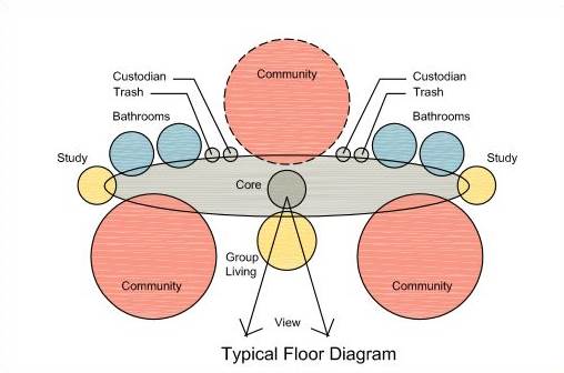
Figure 1. Floor Diagram representation from George Mason University’s Request for Proposal
Major Codes:
General: - ICC International Building Code (IBC) – 2009
- The Americans with Disabilities Act Accessibility Guidelines “ADAAG “– 2004
- CC. USGBC LEED 2009 for New Construction and Major Renovations
- National Fire Protection Association (NFPA) – 2007
Mechanical: - ASHRAE Standard 62-2010 Ventilation for Acceptable Indoor Air Quality
- ICC International Mechanical Code (IMC) – 2009
- ASHRAE Standard 90.1-2010 Energy Standard for Buildings Except Low-Rise
Residential Buildings
Electrical: - National Electrical Code (NEC) – 2008
- ICC International Energy Conservation Code (IECC) – 2009
- National Electrical Code/NFPA 70 – 2008
Plumbing: - ICC International Plumbing Code (IPC) – 2009
Zoning: Must maintain 100’ tree buffer (save area) between site and Roberts Rd per University tree protection agency. Must maintain silt fences to trap job-site runoff from nearby stream 350’ south of site.
Historical requirements of the building: BCOM must approve that the design meets regulations and verify that it matches the design of the surrounding buildings. Traditionally, GMU has a very modern Architecture type.
BUILDING ENCLOSURE
The typical building façade is a weep holed running-bond brick face with an air space, followed by 2” polyisocyanurate building insulation, moisture barrio, spray foam insulation, 6” metal studs, and 2 layers of 5/8” GWB. In some cases there are insulated composite metal panels installed in place of the brick. There are aluminum storefront segments in the multipurpose rooms and on the first floor with both vision glass and spandrel glass. These aluminum storefronts have thermal barrios within them to avoid the creation of a heat bridge. Frosted glass is also used in bathroom areas.
The roofing system is the standard applied to surrounding buildings, as required from BCOM. It is an asphalt shingle system attached to a self-adhering, high-temperature rubberized asphalt underlayment. In areas not covered by the self adhering underlayment, a felt underlayment is to be used. This is attached to blocking and substrate insulation on metal decking.
SUSTAINABILITY FEATURES
The building is expected to meet or exceed DEB Notice 121510 (Virginia Energy Conservation and Environmental Standards) and will exceed 2006 IECC energy standards. It is also expected to implement Green Building educational features, that monitor and display live building power consumption to help influence conservation of energy. Enthalpy Plate Heat exchangers are used in the rooftop air handling unit which help to precondition the incoming outside air. This system is also a variable speed system to slow down air production when the building is in low occupancy. These steps help to reduce energy usage. Combined with usage of local materials, daylighting strategies, low emitting materials, and site sustainability features, the building is currently tracking 58 LEED points and is expected to easily obtain LEED Silver certification.
Building Statistics Part II
Structural
Taylor Hall’s structural system makes use of the patented Infinity Structural System with the intention of schedule acceleration. After talking with a representative from a major specialty contractor who installs the system, this method can be erected a little more than 3 times faster than a standard concrete building.
The foundation of the building consists of shallow footings, as deep as 3’ -4’. Column footings reach dimensions as high as 13’x 13’. Each of the bearing a shear walls on the first floor have their slabs thickened to 1’ deep and 2’ wide on center. The standard slab on grade thickness is 5” for Taylor Hall.
One interesting feature is the elevation change in the slab on grade. Near the elevator pit, the deepest excavation on site (-10’), there is a 4’ elevation difference between the living “community” of the ground floor and the common rooms, office, and laundry room areas.
The superstructure is composed of HSS columns, with a variety of sizes and thickness ranging from 3/8” to ½”. The columns are spliced at the second story and reach a total height from 40’ to 56’. A variety of beams are used to support the Infinity slab system, but not nearly as much as a typical steel frame building would have. The 10’-25’ W12’s in Taylor Hall only accumulate to 18.3 tons of steel.
Infinity Structural System’s in place make use of load bearing, shear bearing, and load/shear bearing cold – formed walls. These walls are panelized into an average of 10’ segments and prefabricated off site. Depending on their application and load, they have 3 5/8” and 5 5/8” thick walls that are 16” off center, and 12” in some areas requiring more bearing. The metal decking is a patented dovetail pattern 20 gage metal, which allows for maximum contact area with the load bearing stud walls. The system is completed with 4” of normal weight concrete slab on deck with 1.5 lbs per SF of reinforcement. Maximum spans using this system allow for columns to be placed as far as 28’ apart.
Mechanical
Taylor Hall’s mechanical system consists of a hydronic heating system that feeds individual units which heat incoming air. The system is tied into the campus’ high temperature hot water system and through two heat exchangers located in the mechanical room. This converts transfers heat to the buildings’ low temperature hot water system for distribution. The temperature drop from heat exchange to the furthest unit is 30 degrees Fahrenheit.
The building is fed from one rooftop air handling unit. The unit feeds the building with 23,500 CFM of 100% Outside Air. Incoming air is preconditioned with an enthalpy wheel for heat recovery and energy savings. The air feeds 3 vertical risers which are then distributed to living areas. For keeping a positive pressure in the building, the exhaust air is less powerful and is taken through above-ceiling plenums in the corridors. Bathrooms have their own exhaust air vent stacks and exhaust fans.
Electrical
Taylor Hall has a total electrical load of 1200A and is fed from a transformer just north of the site. Through underground duct banks, 2 480/277 V 3-phase busses feed the building. After passing through a main switchboard, distribution cables feed 3 panels per floor for residential units. Conduit for each room is run through the concrete slabs on deck. Other electrical loads, such as the elevators and mechanical equipment, have their own electrical panels. The building has a designated diesel powered emergency generator on the exterior of the building to fully power the building in the case of a power outage.
Plumbing
Each floor within Taylor Hall has 2 group bathrooms, each consisting of men’s and women’s rooms. In each bathroom, there are 3 lavatories, 3 water closets, 2 standard showers, and a handicap shower. Each floor also has an individual 3 unit bathroom for the resident associate. The ground floor has one extra group bathroom with 2 water closets and lavatories per gender for the multipurpose room. All waste is tied directly into the campus sewage system located west of the site.