

sssssss
Below is an outline of the general building information for the Gaige Technology and Business Innovation Building along with a list of the project's team:
Building Name: The Gaige Technology and Business Innovation Building Location: The Penn State Berks Campus, Reading, PA Occupant's Name: The Pennslyvania State University Occupancy Types: Univeristy: Classrooms, Offices, Lecture Halls, Student Areas, Labs, and a Kitchen with Cafe Total Size: 64,036 SF Stories above Grade: Three stories above grade Dates of Construction: April 2010 to November 2011 Cost Information: $25.7 million (includes construction, design, inspections, permits, commissioning, and furnishings) Project Delivery Method: Design-Bid-Build
Project Team:
Firm Name Role Website RMJM/Hillier Architect rmjmhillier.com H.F. Lenz Company MEP Engineer hflenz.com Gannett Fleming Engineers Civil Engineer gannettfleming.com Greenman-Pedersen Inc. Structural Engineer gpinet.com Shen, Milsom, Wilke, Inc. Acoustical Consultant smwllc.com Illumination Arts, LCC Lighting Consultant illuminationarts.com Becker and Frondorf Construction Cost Estimator beckerfrondorf.com Alvin H. Butz Inc. Construction Manager butz.com
Architecture
Functionality: The Gaige Building, located at the Penn State Commonwealth campus in Reading, Pennsylvania, is a three story classroom, lab, and office building. It has a large east-west running wing with a somewhat shorter north-south running wing. The main entrance to the building first includes a two story atrium space with open lobby and lounge spaces. The first floor functions as the main classroom, lecture hall, and lab space within the building, being easily accessible upon entrance. Figure one below shows an overview of the first floor with the north-south wing and east-west wing outlined.
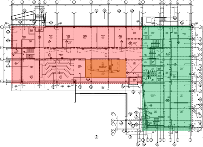 |
| Figure 1: First floor plan with the east-west wing highlighted in red and the north-south wing highlighted in green. Typical layout of building wings on upper floors as well. The cafe area is shown using an orange highlight. |
The east-west wing of the first floor also contains a kitchen and cafe area used by Penn State Berk's Hotel, Restaurant, and Institutional Management Program. The core circulation of the building occurs at the intersection of the east-west wing and the north-south wing, where a vertical stair tower and elevator are located. The north-south wing is also offset at a four foot elevation drop from the east-west wing.
On the second floor, the east-west wing in divided into two main circulation hallways. The lower hallway serves the classroom spaces and contains many open spaces to the first floor below. The upper hallway in the east-west wing serves a large number of faculty offices. The north-south wing on the second floor contains many different technical and computer lab areas. On this floor, there is no elevation change between the two wings.
The third floor of the building only includes the north-south wing. Again, this wing contains faculty offices and conference rooms, as well as one seminar classroom. The floor has two parallel hallways to maximize the amount of offices in the floor’s layout. The east-west wing ends after two floors to provide roof space for mechanical equipment to be stored.
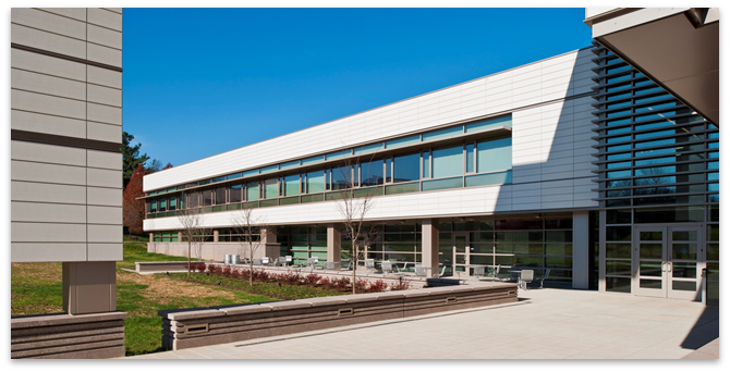
Exterior: On the exterior of the building, the cafe space opens to additional seating in an adjoining outdoor patio space (shown below in figure two). The major architectural highlights of the building's exterior include a three story high, covered, lit entranceway and a garden area, which also collects excess rainwater from the collection system, adjacent to the patio.
Codes: The major national codes used in the design of the Gaige Building are listed below:
| Major Codes |
| Internation Building Code (IBC) 2006 |
| International Mechanical Code (IMC) 2006 |
| International Plumbing Code (IPC) 2006 |
| International Energy Conservation Code (IECC) 2006 |
| International Code Council Electrical Code (ICCEC) 2006 |
| International Fire Code (IFC) 2006 |
The Gaige Building, as it is in Reading, PA, falls under both the Berks County Zoning Codes as well as the local Reading Codes for the specific town. Overall, these local codes mainly reference the national codes listed above, or the national codes provide more stringent doce requirements. As a Penn State Building, it is standard proceedure and deemed necessary to at least follow the national codes standards, unless the local codes are more stringent. In this case, the national codes provide the most stringent case, so they are followed.
Buidling Enclosure
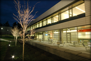 |
| Figure 2: Outside patio area shown as well as the terracotta panels on the second floor. Picture from Illumination Arts with permission. |
Facade Materials: The major elements of the building's exterior enclosure are the curtain walls, windows, terracotta panels, and precast concrete panels. The curtain wall and windows are higher performance windows with aluminum trim integrated into the design. Specifically, the windows are 1.25” ECO insulation glass with heat mirror coating. The performance details are given in the sustainability section below. As well, the major facade element in the design is the terracotta rain screen paneling (shown in figure two above and three below). These panels are naturally waterproof and help to provide a complete building enclosure. Finally, precast concrete panels with integral soffits are used to connect the base of the building to the curtain wall above.
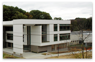 |
| Figure 3: Exterior shot of building entrance, with precast concrete panels shown above. Photograph from PSU Berks with permission. |
Exterior Wall Materials: All of these facade elements are backed by three inches of foil-faced poly-iso board insulation to provide adequate total wall U-value. The exterior facade elements are attached to the rigid insulation using hangers and Z clips. Then, glass fiber sheathing is attached to the rigid insulation, with a vapor barrier in between. The wall materials finish out with cold formed metal framing providing structure to the wall and allowing interior finishes to be attached.
Roofing: For the roofing of the building, the Gaige Building incorporates a complete building enclosure using water-tight materials. This helps to support the rainwater collection system that utilizes the building’s roof as the collection system. First, proper insulation is provided by the same three inch poly-iso board insulation that is used in the exterior walls, and that is attached to an air/vapor barrier system on metal roof decking. The insulation is sloped at 0.25“ drop per foot to roof drains that transport rain water to the underground water collection tanks. Finally, a Kee membrane roofing system provides a complete enclosure to the building’s envelope.
Shading Devices: Around the building, extruded aluminum sun shades are incorporated on the main curtain wall system. The sun shades help to reduce the amount of solar gain experienced in the hottest month of summer, when cooling loads are at a peak. The sun shades are nearly continuous elements around the building on both the second and third floors. Even though no sun shades are present on the first floor, the second floor juts out one to two feet, providing partial shading in the hotter months as well. Figure four below is a picture of the sun shades on the Gaige Building.
 |
| Figure 4: The sun shades used on the exterior facade of the Gaige Building are shown above. Photgraph from PSU berks with permission. |
Sustainability Features
Striving for, and attaining, LEED Gold certification, the Gaige Building at Penn State Berks has multiple aspects that feature sustainable design and construction practices. These sustainable practices includes a rainwater harvesting and reuse system, advanced building control system, heat recovery, high performing thermal windows, high efficiency fixtures, and environmentally conscious material selection.
Rainwater Harvesting: The building’s roof is designed to collect rainwater and transport it to two underground, 35,000 gallon rainwater collection tanks. The grey-water from these tanks is used to flush toilets, water plants, and clean the exterior facade of the building.
Advanced Building Controls: At the forefront of building control systems, the building contains daylight and occupancy sensors to control the energy usage by the lighting system throughout the building. The hallways have daylight sensors to control the levels of light required when daylight is available, and occupancy sensors turn off lights in rooms that are not in use. The design also allows for natural daylight access to 95% of the building.
Heat Recovery: The three air handling units that serve the building are equipped with energy recovery devices to recover thermal energy stored in the building’s exhaust air.
High Performance Windows: The curtain wall facade of the building is made up of 1.25“ insulating glass that has argon-filled cavities to achieve an extremely low U-value. The glass performs at U = 0.11 maximum in the winter, and U = 0.26 maximum in the summer. Also, a heat mirror coating is added to the glass to improve its summer performance.
High Efficiency Fixtures: Both high efficiency water and lighting fixtures are used throughout the building’s design. As well as using grey water to flush toilets, low flow fixtures are implemented to reduce the amount of potable and grey-water used in the building. LED fixtures help to reduce the annual electrical demand of the building, and in turn, annual operating costs.
Materials: In order to reduce the heat island effect, light colored pavers, terracotta paneling, and a white roof are implemented into this project’s design. The Gaige building also uses materials containing recycled content in 20% of the total construction materials used.
Mechanical
Overall System: The Gaige Building has three main root top units (RTU-1, RTU-2, and RTU-3) that provide ventilation, conditioning, and exhaust for the majority of the spaces within the building’s design. The units are sized to 20,500 CFM, 14,000 CFM, and 12,500 CFM respectively. Each of these units serves a variety of spaces within the first, second, and third floors of the building. Air is supplied from the roof top units at a supply temperature of 55 degrees, and it is ducted throughout the building.
Zone Control: At the individual spaces, variable air volume boxes are provided for each zone. The VAV box takes the 55 degree air, and varies the volume of air being supplied to the space to meet the cooling requirement of the space at the current time. The load is monitored by a thermostat located in each of the zones separately. CO2 and occupancy sensors also are coordinated with the VAV boxes to allow for a reduction in outside air required to be supplied to each space. A minimum set point prevents the VAV box from supplying air less than the minimum outside air requirement for the space. A reheat coil prevents from overcooling the space when providing minimum outside air at a time when cooling requirements are reduced.
Heating and Cooling System: Two 1300 MBH boilers provide the hot water service for the building and all mechanical heating requirements. Four split system air conditioners are required to provide individual space cooling for the telecom/data rooms in the building, and one computer room air conditioner is required for the IT storage and equipment room, also supplied with an air-cooled chiller. Unit heaters are provided throughout the building as needed in semi-heated spaces, such as the vestibules at the building entrances. Finally, the heating loads for the building are met by radiant-heating panels and fin-tube heat exchangers placed at exterior walls of spaces that don’t experience a year round cooling load. This allows for simultaneous heating and cooling throughout the building in spaces that contain these heating elements.
Lighting/Electrical
Lighting: In the Gaige Building, CO2 sensors and occupancy sensors are provided not only to help reduce mechanical system efficiency, but to control the lighting system as well. The sensors are set to automatically shut off the lighting after a period of time when a space is unoccupied. The range of time before shut off is an adjustable setting. The Gaige building lighting system is compliant with the maximum Watts/SF allowed by ASHRAE 90.1. The allowable watts are at a set point of 0.99 W/SF coming to a total maximum value of 63.4 kW, and the Gaige Building comes out to a total of only 53.6 kW, meeting this requirement. The lighting in the Gaige Building consists of mainly fluorescent bulbs, but also contains halogen bulbs for some decorative applications and LED lights in a few spaces.
Electrical: The electrical system in the Gaige Building is first run from the utility to a 1200 A main distribution switchboard through four sets of three 350 kcmil feeders, supplying the building with power at 480/277 Volts. From this system, 480/277 V panel boards supply power to services like the mechanical equipment and other larger building systems. Also, a transformer is provided to step the power system down to a 208/120 V system to supply power to lighting panels, receptacle panels, etc. The Gaige building is in compliance with the 2006 National Electric Code, and all of its power requirements are met, along with the additional requirements set forth is section 8 of ASHRAE Standard 90.1. All required documentation of the building system design and equipment manuals have been provided as well. The emergency system is supported by a 85 kW natural gas generator supplying power at 480/277 V to emergency lighting and equipment panels.
Structural
The substructure of the Gaige Building consists of a slab on grade construction rated at 4000 psi. The foundation system connects the slab construction to the buildings micro-pile system through grade beams connected into pile caps, for both tensions and compression. Above the substructure, the superstructure consists of steel construction and composite floor deck. The superstructure uses a continuous slab-beam design. Apart from this, the decking is designed for shored construction and non-composite rook decking. For lateral loading, the Gaige Building uses a combination of X braced frames and eccentric braced frames. This allows for most of the connections in the building to be shear connections, no required to hold moment and support the building laterally. One unique aspect for this building is the structure for the heavy terracotta panels which compose a large portion of the building's facade. These heavy elements of the facade set on steel girts for added support for the curtain wall.
Construction
The Gaige Building utilized a typical design-bid-build project delivery method, and the construction was managed by Alvin H. Butz Inc. based out of Allentown Pennsylvania. Despite the typical project delivery method, a comprehensive project management plan was utilized to keep the building on schedule and keep good communication of expectations between owner and the different project teams. One major change to the building plan was the need to enclose the building by January of 2011, so internal systems could begin interior work on the project. To do so, overtime was paid and work was continued during the winter months. To do so, the roof system was also switched to an asphalt coated system to allow the material to be heated and installed during the middle of January. Construction was completed in 369 working days, more than two months ahead of its original schedule, and it came in under budget.
Additional Engineering Systems
Fire Protection: The Gaige Building is protected from fire using both active and passive systems. First, the Gaige Building contains a wet-type sprinkler system on all building floors, providing semi-recessed pendant type sprinkler heads in all public areas, corridors, and toilet rooms. As well, for other space types, such as mechanical, storage, and electrical rooms, quick response upright sprinkler heads are provided. Standpipes are provided next to the two enclosed stair towers in the building along with all necessary equipment. Passively, all of the Gaige Building's construction typologies are rated to the appropriate fire stop rating, and all openings are fire stopped to provide for a continuous fire barrier between floors. These types and UL ratings are specified in the construction documents. The entire system is classified as a type IIB building, which provides for its construction requirements.
Transportation: The building contains one elevator, located at a central lobby area within the building. This elevator serves each floor of the building, providing for accessible access to the entire building by all occupants. As well, due to a slight elevation change between building wings on the first floor, the elevator is positioned to open on each side of the first floor for each building level, providing access to the entire first floor, despite the four foot elevation difference.
Telecommunications: The Gaige Building provides is routed in cable runway throughout the building above corridors to all classrooms, offices, and labs. Since this is an education building, it is imperative that the telecommunication system provide access to data connections throughout the building. A telecommunication room first floor provides as a distribution point for floors one and two, and floor three contains its own telecommunication room. The rooms contain one backbone rack with multiple other horizontal racks for data distribution.
Buidling Security: The Gaige Building is equipped with special security systems to eliminate key requirements for the building and provide extra security. PSU ID card readers are equipped throughout the building, providing easy access for students and faculty to room and building areas as needed. This system automatically shuts down when the building is closed, and can be shut off in the event of a security emergency. This provides for improved safety and security of the building during emergencies and non-operational hours.
Contaminant Removal: Overhead units remove contaminants for labs and rooms used for welding, grinding and sanding, ensuring a high level of indoor environmental quality. As well, all caulking, sealants, and glues used on the project were rated to have a low level of volatile organic compounds, and a large portion of the flooring in the Gaige Buidling is simply polished concrete, containing no finishes that could introduce unwanted compounds to the building's environment.