building stats
+ Name:
The Frederick College of Cardiology
Location:
Arlington Heights, IL
Occupant:
The Frederick College of Cardiology (Fictitious Name)
Type of Building:
Office/Professional Learning Facility
Size: 48,500sf
Number of stories above grade:
2
Primary Project Team:
Owner - The Frederick College of Cardiology
Architect - Perkins and Will http://www.perkinswill.com/
General Contractor – Pepper Construction Company www.pepperconstruction.com
MEP – WMA Consulting Engineers http://www.wmaengineers.com
Dates of Construction:
January 2013-?
Actual Cost of Construction:
Cost not available at this time
Project Delivery Method:
Design-Bid-Build
Design and Functional Components:
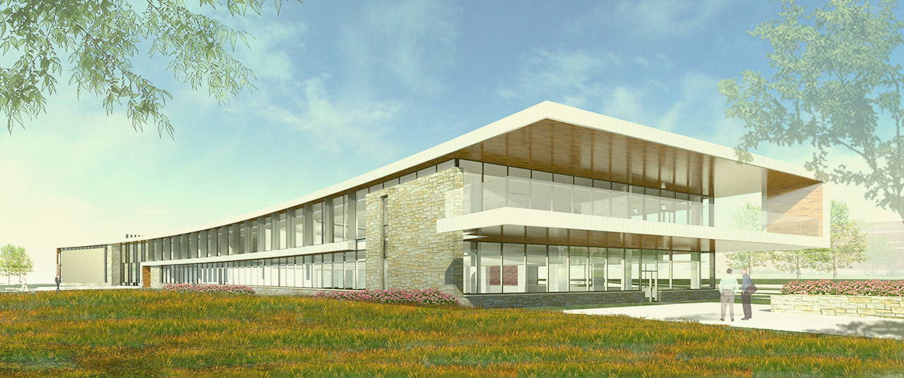
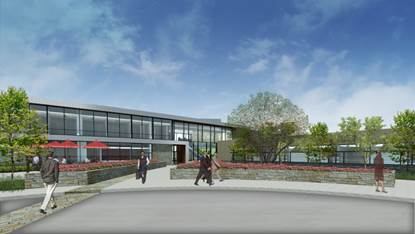
The Fredrick College of Cardiology houses offices, labs, operation rooms, and an auditorium. It is a multipurpose facility built for the effective instruction of surgeons. The building rises two floors above grade keeping a low profile along its exterior. The floors lay out in an L shape spreading from a main hub where the main entrance and auditoriums are located. Classrooms, labs, and operation rooms are kept on the eastern leg of the “L” while the southern leg contains the offices and eating areas. The proposed design allows for integration of many learning facilities into one streamlined architectural design.
Building Facade
The building enclosure is made up of glazing, stone, brick, wood, and metal sheathing. Large portions of fenestration create the East and West walls of the lobby and extend along the sides of the building providing natural light for the office and classroom spaces. Low – E glass is used to reduce solar heat gain. Wood accents are present on the underside of the overhang on the southern terrace. The edge of the facade which wraps around the extents of the building is made of metal sheathing. Stone and brick cover the remaining exterior sections of the building facade.
View Facing NW
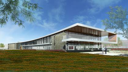
View Facing NE
Roof System
The roof system is made of steel trusses which support steel decking. The roof is weather-proofed with a flexible membrane.
Exterior Solar Shades and Interior Shading Systems
The southern facing facade employs static solar shades to reduce solar gain.
Interior shades are present in the office and classroom areas and are controlled by a Lutron system.
Lighting
Lighting design and equipment selection for this facility create visual continuity and promote energy efficiency. Many linear and compact fluorescent lamps are used as well as several LED and metal halide sources. Lutron control systems regulate lighting usage and shading operation. The double auditorium requires flexible controls to adapt lighting to be for two separate spaces or one large space. Mock operation rooms require significant amounts of illumination to meet the criteria for medical surgery. Daylight will be a large component of the interior lighting system and will be controlled by motorized shades.
Electrical
Power to the outdoor Utility Transformer arrives at 12kv and is transformed to the building utilization voltage which is 480/277Y. The utility transformer sends power to the main switchgear and fire pump controller. The main switchgear (1-SWBD-1) is rated at 1600A and connects to two step-down transformers, one HVAC distribution panels, and two automatic transfer Switches. The step down transformer for the education wing lighting and receptacle loads (T-EDU-1-LDP-1) transforms 480Y/277 to 208Y/120, is rated at 225kva, and outputs to distribution panel EDU-1-LDP-1. The step down transformer for the office wing lighting and plug loads (T-OFF-1-LDP-1) transforms 480Y/277 to 208Y/120,is rated at 150kva, and outputs to distribution panel OFF-1-LDP-1. All lighting and receptacle loads operate at 120V. The HVAC distribution panel for education wing and office wing HVAC loads (EDU-HDP-1) is powered at 480Y/277 and is rated at 400A. HVAC equipment operates at 480V. The backup power system is switched from switchgear 480Y/277 power to 480Y/277 back-up generator power in the event of a power interruption by two ATS switches (EDU-ATS-2 & EDU-ATS-1). Two step down transformers following the ATS switches convert 480Y/277 to 208Y/120. The back-up system powers emergency lighting, the UPS system, emergency communication equipment, and emergency HVAC equipment. Specialty equipment including fire alarm System, rescue communication system, electronic door lock system, ad A/V equipment all operate at 120V.
Mechanical
Cooling in the building is provided by two 100 ton cooling towers located on the roof. Heating is provided by two natural gas boilers located in the basement. Supplemental cooling is provided to the server room, AV room, and IDF room by split system air conditioning units. Supplemental heating is provided by six hot-water cabinet unit heaters and six hot-water unit heaters, located throughout the building. Additional air delivery control is provided by both fan powered boxes (FPB) with hot-water reheat and variable air volume (VAV) units with hot-water reheat.
Structural
The main structural system consists of steel framing with concrete decking. The southern wing of the building contains steel wide flange beams that span 3, 20’ bays East to West and 30’ bays North to South. The southern wing curves slightly to the west with a maximum radius of 4.1 degrees. The longest span for the west wing is 40’ and the typical span East-West is 20’. The concrete floor slab is made of 4” thick poured concrete on 3” metal decking. A 4' thick poured concrete floor slab supports the building.
Telecommunication and Fire Protection Systems
The building is equipped with an emergency intercom system which relays information to occupants of the building. The fire protection system includes a fire pump operating on emergency power and a full alarm system.