General Building Data
| Name | Heifer International Center |
| Location | Little Rock, Arkansas |
| Occupant Name | Heifer International, Nonprofit |
| Size | 98,000 sq.ft. |
| Number of Floors | 4 stories |
| Height | 65 feet |
| Construction Dates | Feb. 2004 - Jan. 2006 |
| Approximate Cost | $18 million |
| Project Delivery Method | Const. Management at Risk |
Project Team


Architecture
Heifer International’s headquarters is located in Little Rock, Arkansas and emulates Heifer’s goal of reaching out to a community in need. Heifer wished their headquarters to match what they were teaching to the world—Jo Luck previous president of Heifer International articulates, “Nurturing the environment while combating hunger have always gone hand-in-hand with Heifer.” The product of this nonprofit organization’s philosophy led to one of the most unique and sustainable buildings in the United States, at its completion.
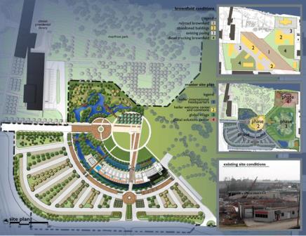
The shape of the building and campus were inspired by Heifer International’s founder Dan West who expressed, “In all my travels around the world, the important decisions were made where people sat in a circle, facing each other as equals.” This was extended to show the ripple affect Heifer has on needy communities, through their donation of livestock. These communities agree to pass on the offspring of the animal to others—thus creating a ripple affect throughout the community
The building provides an open floor plan that allows natural light to penetrate to the center of each floor, provides views of the river and cityscape, and offers extensive community exchange points with easy access to exterior balconies on each level. Heifer International Center continues Heifer’s mission of teaching—the public is allowed access to the facility through tours provided by Heifer personnel, showcasing the sustainable features of the office building.

Heifer International Center rests at the site of a previous industrial section of Little Rock. A 22 acre railroad switching yard, that was originally covered by 13 acres of concrete and asphalt, was a brownfield. Funding through the Environmental Protection Agency led to the brownfield’s cleanup—the removal of 75,000 tons of earth, and allowed for the construction of the building and surrounding campus. The architecture and landscape of the building and campus allows for public education of environmental responsibility and sustainable design and construction. Heifer International coordinated their design and construction with the William J. Clinton Presidential Library & Museum. The campuses combine to form almost 60 acres of green space and gardens that have a spectacular view of the Arkansas River and Little Rock skyline.
Building Code
The International Building Code 2000 classifies the building as Business Group B, Type III with a maximum height of 75’-0”. Additional codes referenced include:
- Standard Mechanical Code 1997
- Standard Electrical Code 1997
- Standard Plumbing Code 1997
- National Electrical Code
- Americans with Disabilities Act
Zoning
Little Rock, Arkansas classified the industrial section of the city as a POD, Planned Office. The building was zoned to be a Group B Business Office Building.
Additional zoning requirements requested.
Historical Requirements
There are no unique historical requirements for this building.


Building Enclosure
Building Façade
Heifer International Center’s façade is composed of a standard curtain wall system that spans vertically between the floors. The glass is produced by Guardian Industries of Auburn Hills, Michigan, and was fabricated by Ace Glass Co Inc. of Little Rock. A SunGuard SuperNeutral 68 low-emissivity coating was placed on the glass. This coating aided with reducing heat gain, but still allowed daylight to penetrate the building. The glass had the following properties:
Glass Properties:
- U-value of 0.29
- Heat gain coefficient of 0.38


Between each level is a spandrel panel, that is clad with corrugated aluminum panels, PAC-CLAD Silver Metallic 7/8”. These were used as horizontal accent bands to frame the glass at the different levels of the building.
The curtain wall systems also includes sunshades, that were also from a standard system of the curtain wall system company.

Additional information requested from architect and engineer regarding façade.
Roofing
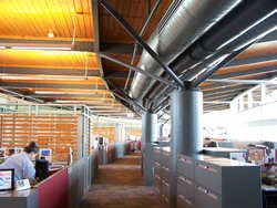
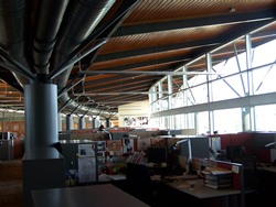
A unique feature of the building includes the use of custom tree-column design that is used to support the inverted roof at both exterior and interior points. The roof is inverted for two reasons. The first is to direct rainwater towards the large silo-tower for storage and greywater use. The second is to provide the ideal angle for a possible future solar panel array.
The roof is composed of a Thermoplastic Membrane, topped with a 4" Glue Laminated Wood Decking. The wood decking uses a tongue-and-groove, and is connected to 3" of continuous wood lumber using 8d nails at 6" O.C. The wood decking is Ponderosa Pine, with a nominal size of 4" x 6". This system is then bolted to the top flange of the roof steel members.


Additional information requested from architect and engineer regarding roof’s structural and architectural components.
Sustainability
Heifer International Center was placed in an industrial section of Little Rock that is currently being revitalized. This led to many advantages that the design team used to the building and site’s benefit. The site that Heifer International Center occupies was contaminated with industrial waste. Through land reclamation, the soil was removed from the site and taken to a facility to be treated and used elsewhere in the Arkansas region. The industrial section of the city also housed the steel mill that manufactured Heifer International’s steel structure—AFCO Steel Inc. is located only a few blocks away from Heifer’s site. Moreover, the mostly glass building utilized Ace Glass Co Inc. as the fabricator of the glass, located less than a 100 yards from the building.

The fabricators’ close proximity to the building’s site greatly reduced the carbon footprint of the construction phase. However, the construction phase is only one small phase of the building’s entire life. An integrated architecture, lighting, electrical and mechanical system aided Heifer International Center to use 55% less energy, than a comparable building.
Heifer International Center was able to achieve a LEED Platinum. The design used the following:
- The unique shape of the roof diverts water to a five-story tower-silo, capable of storing greywater for use inside the building
- Permeable paving redirects rainwater to bioswales surrounding three sides of the building
- Light and occupancy sensors minimize energy usage
- Under floor air distribution system allows air to rise naturally as it heats, and then returns at the ceiling
- Natural light penetrates into building, using light shelves; however, blocks heat gain and direct sunlight
- East/west orientation of the building and the semi-circle shape allows the sun to be “tracked” during the day
- Waterless urinals
- Recycled Denim Insulation Radiant Barrier
- Low-VOC Materials for office furniture
- 97% recycled steel structure

An astonishing 97% of the existing building and site work were recycled—not only saving the material from being wasted in a landfill, but generated revenue that helped pay for the demolition. The construction of the new building managed to recycle 75% of the construction’s waste, by weight.
In addition, bricks and other materials found during the reclamation project were incorporated into different sections of the site’s landscape, paving and into aesthetic locations along the exterior of the building. The landscaping of the previous switching yard was converted to a wetland, restoring the site to its natural state.
Primary Engineering Systems
Structural
Grubbs, Hoskyn, Barton & Wyatt, Inc. performed a geotechnical survey of the site in January of 2003. The survey encountered expansive clays on the east side of the building and soft and compressible soils on the west side of the building. Expansive clays expand when they gain water, and contract when they lose water—potentially heaving, or raising, the site elevation 4" to 8". On the east side, the report recommended that the weak soils should be undercut during site grading—approximately 4'-0" to 6'-0". Undercutting involves removing the soil to the specified depth and replacing it with engineered soil, which is compacted. The soil removed would be replaced with low-plasticity clayey sand, sandy clay or gravelly clay. The geotechnical engineer stated that undercutting would allow the use of a slab-on-grade system; however, the use of two potential systems to increase the bearing capacity of the soil would have to be implemented.
The geotechnical engineer recommended either Rammed Aggregate Piers or Drilled Piers, for the foundation system. A Rammed Aggregate Pier® (RAP) System by Geopier Foundation Company, Inc., is used to mechanically improve the soil conditions of the site. The RAP system uses "vertical ramming energy" to add layers of crushed aggregate to the site. Generally, Geopiers™ are formed by drilling 30-inch diameter holes and ramming aggregate into the hole, until a "very stiff, high-density aggregate piers" are formed. This crushed aggregate increased the soil's capacity to between 5 to 7 ksf for the Heifer International Center. Additional Geopiers™ were provided per structural drawings, due to larger loads or the higher potential for uplift at certain sections of the building. The geotechnical engineer stated, "Total settlement of shallow footings on Geopier™ elements would be expected to be less than about 1.0 inch and differential settlement less than about 0.5 inch."
The design teams chose a RAP® System, which allowed the use of conventional slab-on-grade, footings and grade beams. The RAP® System had the added benefit of increasing the bearing capacity and decreasing the size of the footing.
This system was applied to the entire building footprint. Both a typical and sloped slab-on-grade were used, and are reinforced with welded wire fabric. The slab-on-grade fluctuates in depth at many locations due to various loading conditions used throughout the building.
Heifer International Center also is provided with grade beams to distribute loads to column piers and footings. These grade beams support the slab and prevent the slab from deflecting or settling. The design uses various sizes of grade beam, which are reinforced using #4 stirrups at 24" O.C.; #5 and #8 longitudinal reinforcing bars are also used.
Heifer International Center's floor system is composed of girders and beams supporting composite steel deck filled with a concrete slab. The greater part of the beams supporting the floor system is W14x22s and W16x26s. Each beam has a camber ranging from ¾" to 1". The framing nearer the center of the building is irregular due to the large interior architectural opening, walkway bridge and lobby space. The framing at each end of the building, on the east and west, is also irregular due to the large mechanical spaces, cantilevered balconies and stairwells. The mechanical spaces are generally supported by W16 beams.
A typical bay is 20'-0" x 30'-0", with 5 ½" total concrete, on 20 gauge composite deck. This is supported by W shape beams, which transfer their loads to girders. The composite deck is 3VLI with 2 ½" of normal weight concrete topping. The decking compositely acts with the framing members to take advantage of concrete in compression and steel in tension.
 to irregular framing layout (blue)")
The framing system consists of large round HSS shapes, which continue from the ground level to the fourth floor. Originally concrete columns were considered; however, the contractor and steel fabricator where particularly concerned about maintaining tolerances on concrete columns, and the attendant difficulty of connecting to the beams. Due to these concerns, the design was changed to round steel, HSSs, which vary from 10" to 24".

Lateral stability is ensured in part by the floor deck, which acts as a diaphragm spanning between steel plate shear walls. Steel plate shear walls (SPSWs) resist horizontal shear, and effectively act as a vertical girder—the columns act as the flanges and the steel plate acts as the web. The SPSWs span from the foundation to the bottom of the fourth floor. The floor slab is also reinforced with additional #6 at 5" O.C. to help with diaphragm action of lateral loads.
Due to the irregularities of the building's shape and the 440'-0" length, the semi-circular building was divided into two approximately even sections with a seismic joint. These two halves were analyzed separately for lateral loads, using both static and dynamic methods. Essentially, two separate structures, with separate lateral systems, are joined together to act was one unit.
Mechanical
Heifer International Center uses a Variable Air Volume Underfloor Air Delivery System (UFAD). The raised floor system allows for higher efficiency, because it requires only a small amount of pressure, and also provides a space to run cables and other conduit systems throughout the building. Raised floor also improves indoor air quality and efficiency by delivering the air low and returning high. Two ventilation units provide outside air to the mixing boxes of each UFAD unit. There are a total of eight UFAD units (two per floor), where a single ventilation unit serves four UFAD units. Each UFAD unit is controlled by temperature, humidity, CO2 and pressure sensors, which constantly monitor the environment of the building, and make the correct adjustments with a Direct Digital Control System. The UFADs can supply between 6,500 and 14,500 CFM to the various levels of the building.
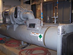
A high efficiency centrifugal compression chiller, using HFC-134a as the refrigerant was chosen for the building, to supply 300 tons of cooling. The system uses a variable primary pumping system, limiting the flow to the chiller. This, in combination with a heat exchanger to reduce the load on the chiller, saves approximately 73% of the energy required by a ANSI/ASHRAE/IESNA Standard 90.1-2001 building.
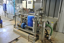
Hot water is provided by two pulse-combustion high-efficiency boilers. Water usage and collection is regulated by a system of storage tanks and pumps. Rainwater falling on the roof is stored in an exterior 20,000 gallon tank, an inverted silo acting as a large stair tower in the middle of the building. This water can be used to offset potable water usage. Water is also recylced from lavatories, showers and ventilation units. This water can then be used to flush toilets and provide makeup water to the cooling tower.
Electrical & Lighting
Utility enters the building through an equipment yard located on the site, transforming the voltage into 480Y/277V. The total system is 2000A, of which 400A is transferred to the fire pump and 1600A is transferred to the building. The 1600A transferred to the building travels to the Main Distribution Panel (MDP) running at 3-phase, 4 wire system. This powers various larger systems throughout the building, such as mechanical spaces, and interior and exterior lighting. The voltage is stepped down to 208Y/120V, which powers most of the underfloor air distribution systems, occupancy and photometric sensors, conference communication equipment, and mechanical and smoke louvres and dampers.
The 400A that is transferred to the fire pump, is also supplemented by a backup generator. This backup generator supplies 200kW to the building, or 700A total. The remaining 300A can be transferred to an Emergency Distribution Panel (EDP), which powers emergency lighting and signs throughout the building.
The lighting for Heifer International Center runs at 277V, with a few exceptions using 120V. The main lighting fixture uses a 4'-0" office luminaire, which uses two (2) T8 lamps, hung using an industrial chain. The lobby spaces on each level use a combination of troffers for direct light and indirect wall mounted luminaires and a curved track lighting system. The track lights use 120V, while the troffers and wall mounted luminaires use 277V. Each space in the building is governed by two sensors, an occupancy sensor and a photometric sensor. The occupancy sensor can detect if someone is present in the room, and if no one is present, shut off the lighting. The photometric sensor measures the amount of light in each space, and compares it to a preset value. If the value is met from the natural lighting, then the luminaires are shut off. If not the luminaires are kept on, if the occupancy sensor confirms the space is occupied.
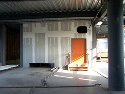
Construction
Heifer International Center was constructed by CDI Contractors, LLC, of Arkansas, under a Construction Management at Risk project delivery. The building's final height was 65'-0", and was constructed between February 2004 and January 2006 at the cost of approximately $18 million. The building's final square footage was 98,000 sq. ft., at four stories tall.
Support Systems
Fire Protection and Alarm System
The Heifer International Center was designed to follow the IBC 2000 Fire-Resistance Rating Requirements. With a Type III B Construction with steel framing, the building was not required to have structural framing fire ratings. Only bearing exterior walls were provided with a two hour fire rating; however, a wet fire suppression system is used throughout the structure.

Transportation Systems
Two passenger elevators, one freight elevator and three stair towers are used for conveyance throughout the building.