Kathryn Gonzales
Construction Management
| Building Stastics 1 |
|---|
General Building Data |
Building Name: Health Sciences Facility III Project Team
Construction Manager: Barton Malow Architect: HOK Associate Architect: Design Collective MEP Engineer: AEI Structural Engineer: Cagley & Associates Interior Architect: Melville Thomas, Inc. Civil Engr/Landscape Arch: Site Resources |
Architecture |
The building is divided up into four main areas, as seen in Figure 1 on the right. In the core there are 4 elevators, one of the main mechanical shafts and a stair tower. The north and south tower hold the main program space while the atrium serves as a bridging point between the two towers.
courtesy of Barton Malow |
Codes |
2012 International Building Code (IBC) |
Zoning |
A zoning study was not performed by the civil engineer because the building is on a school campus. courtesy of the University of Maryland
|
Historical Requirements |
There are no historical requirements for this building. |
Envelope |
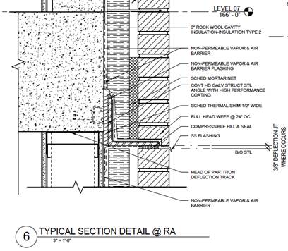
The makeup of the brick façade includes the brick, a 2” air barrier, insulation, vapor barrier, sheathing and 6” metal stud backup. The precast is located mainly on the north face and the core of the building. There is a large metal panel fin that sticks out in the north elevation that acts more as an aesthetic piece. One noticeable difference of the precast detail compared to the brick wall is its elimination of the air barrier replaced with a cementitious thermal barrier. The precast is also thicker than the brick at 6”.
There is a small relationship between the brick and the precast on the north façade, but the main integration of multiple materials is seen through the curtain wall and precast on the south façade. Curtain wall is the façade type on the south to take advantage of the natural sunlight that comes from the south. All of the windows throughout the exterior of the building are made of a low e insulating glass, and the punched openings will have a louver shading system as needed.
Above the roof level, the envelope extends as a parapet forty-three feet to hide the mechanical equipment located on the roof. This is concealed with louvers encased with precast and brick. On the ground floor surrounding the entire building, granite replaces a large chunk of masonry as the primary façade type.
courtesy of the contract documents |
Roof |
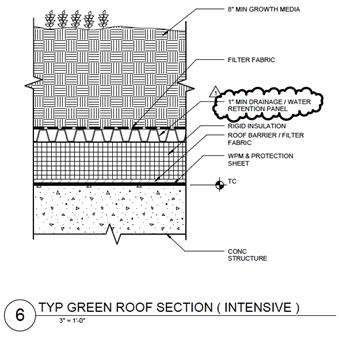
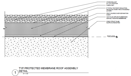
As previously mentioned, there are two types of roofing systems on this building. The main type is an IRMA system that consists of a hot fluid applied asphalt membrane followed by insulation, a fabric mat and ballast stone. An 8” thick slab of concrete supports this. The second kind of roofing system is a green roof. There are multiple locations and levels that this green roof exists. Its main purpose is to collect rainwater and divert it into the appropriate systems as well as provide thermal insulation. Most of the green roofs have 8” of soil separated by a fabric and a water retention panel. Underneath the retention panel, the roof follows the same makeup as the IRMA roofing system.
courtesy of the contract documents |
Sustainability Features |
In the case of HSF III, the green roof is a major sustainability item because of its thermal capabilities as well as reduction on the heat island effect. The project team is currently pursuing a LEED Silver certification, and through this the construction management company is tracking waste removal from the site as well as construction materials and their VOC content. There have been multiple value engineering exercises done between those involved in construction and the designers to help reduce the overall cost of the building as well as propose different systems that perform at the same or a better rate. |
Building Stastics 2 |
Construction |
The main delivery system used in this project is a CM at Risk with a maximum GMP. This type of contract is held with the construction manager as well as 4 design-assist subcontractors. They include the concrete, curtain wall, mechanical and electrical contractors. Barton Malow, the construction manager, was brought on board shortly around the schematic design phase after which the design assist subcontractors soon followed. Their main purpose is to provide expertise on schedule, cost, and constructability at each design stage. They also participate in the coordination of drawings. All other subcontractors for the job are competitively bid. The design team has a traditional fixed fee contract structure. The project is also considered fast tracked construction because the demolition and excavation began before the design was completed. The tower crane is located in the atrium space and fits within the hole of two designated skylights for the space. It is planning on staying in action throughout the erection of the exterior envelope. Once the building reaches the eighth floor, it will have to be raised another eighty feet to reach its final height. During peak times of crane usage, there is potential for two shifts to work with the crane. This plays out when the concrete is using the crane on the upper floors while the precast and curtain wall have started on multiple faces of the building. One material hoist will be located on the west side of the building, obstructing about a third of the façade. There will be a temporary loading dock beside it to allow for material deliveries. |
Electrical |
The main electrical room is located in the basement where it receives the dual redundant 13.2KV feeders. For construction related power requirements, a temporary switch on N Fayette will be located. Based on the design information, the anticipated load of the building is 7,447 KVA. There are four main switchgears at 100 KAIC, 5000A and 480/277 wye. Two serve as backup generators and the other two service the entire building. Each distribution panel for the lab spaces has an emergency distribution panel on the same floor. The main distribution of power throughout the building comes from two electrical rooms on each floor. They act somewhat like a shaft up the center of the building on each side that it services. There are multiple distribution panels on each floor. These panelboards service each of the following items: receptacles, lab receptacles, equipment, lighting, and emergency power. Most of these panels are 100A with the exception of the lab power supply panelboards at 225A and 120/208 wye. For the lighting and the equipment panelboards, their voltage is 480/277 wye. |
Lighting |
With a high surface area of curtain wall on the south end as well as the use of skylights in the atrium space, natural light is an important feature to the project team at HSFIII. Many of the offices face the south curtain wall and can take advantage of that direct light while the open spaces in the labs are located in the north allow indirect light into the space. Recessed grid mounted fluorescent lights will be used in the open lab spaces because those spaces need a high concentration of light. A typical office space has one pendant hung fluorescent light. The conference rooms match a similar layout to the open lab spaces. Emergency lighting in the space is generally small square recessed fixtures or linear fluorescent fixture mounted on the wall. |
Mechanical |
There are three major categories for the mechanical systems located in the penthouse of the building. Four air-handling units service the lab spaces with a 100% DOAS system at 64000 CFM. Two air-handling units service the vivarium with the same type of DOAS system that the labs have at 63000 CFM. Finally, the last two air-handling units service the offices space in a mixed air system with 35% outside air at 38000 CFM. All of these systems have airside economizer controls, reheat coils, chilled beams and VAV units. For the vivarium space, the source of energy is a humidification steam generator that also services the booster humidifiers. The existing chilled water system is not sufficient for the capacity of the new building, but the new building will tie into that system as for redundancy and as an emergency loop. The four chilled water systems are electrical driven, water cooled, and variable flow. They service the air-handling units. Due to the nature of a lab space, there are several other systems that are involved in the mechanical space. One of these is a process cooling water system that is used for the water-cooled equipment in the lab spaces in addition to the cold room compressors found. For the reheat system, HSFIII has glycol heat exchangers and reheat coils in the fin tube radiators around the perimeter and the chilled beams. Four fiberglass cooling towers on the roof exist to service the chillers and are double cell, counter flow and induced draft. |
Structural |
HSF III has a mat foundation because of the high water table. The building embodies a bathtub concept: the 44”-60” mat slab acts as a massive weight to anchor the rest of the building to the soil, allowing water to freely pass around it. The waterproof membrane that wraps around the building must be dry when applied, which makes the dewatering efforts critical for this process. This extends all the way up the foundation walls whose forms are built on site with a mix of plywood and reusable forms. There are several shear walls in this building, mostly located near shafts, elevators or stairs, which acts as a stiffening agent to the building. The pouring schedule of the mat slab is in eight sections and the forms are built in such a way that each joint between pours fits together like a puzzle piece. The entire superstructure is cast in place concrete that span on average about 21 feet. The elevated slabs are primarily 8” in thickness at 5000 psi with the exception of the 10” slab within the core on all floors. Most of the stairs are made of precast or miscellaneous metal. From the foundations to the 5th floor, the placement method of the concrete will be pumped, while the higher floors will be crane and bucket due to pumping height limitations. It is preferred that many of the major pours will be conducted on a Saturday due to less traffic in the downtown area as well as more availability from the batching plant. Reusable forms will be used on most all of the columns and shear walls. Re-shoring of the slab is a host of scaffolding to support the weight of the structure while it gains in strength over time. There is a unique moment of steel framing at the intersection of two curtain walls in the atrium. Hollow metal steel is used to create this horizontal truss to brace the glass, specifically HSS6x4x1/4. A massive HSS6x6 mega column supports each truss in the atrium. There is also a mix of W8x10 and W18x40 steel beams around the atrium skylights on the seventh floor. |
Fire Protection |
Some of the two hour rated spaces include the shafts, stairs, elevators, and the main switchgear room. Many of these types of spaces span most all the floors and are most likely to spread a fire. One hour rated partitions are for all of the electrical and mechanical rooms, the firs command center in the building, and chemical waste storage. The oil tank room is a hazardous space and requires three hour partitions around it. Within the atrium there are storefront windows that separate the atrium from the north tower. They will be serviced by a water curtain with sprinkler heads spanning no greater than 6 feet. Floors 5 and 6 are shell spaces and will have upright sprinkler heads where the ceiling is exposed all the way up to the metal deck. This is in anticipation of the future use of the space. The lab spaces are considered ordinary hazard, group 2 while the rest fall under the group 1 category, according to NFPA 13. The stairs are a mix of wet and dry standpipes, depending on the location of the stair tower in the building; there is also a dry standpipe at the loading dock. To connect to the water system in the building, the fire department can access connections both at the southwest corner and northeast side. Copper piping and fittings are located in the shielded imaging rooms because these spaces imitate requirements for an MRI suite. An 8” pipe of incoming fire service located on the southwest corner of basement includes a double check backflow preventer on the building side. Standard piping is required at pressure less than 175 psi, while high pressure piping will be used when greater than 175 psi. |
Transportation |
courtesy of the contract documents |
Telecommunications |
All of the data routes back to two IT rooms per floor, each one servicing either the west or east wing of the building. There are plenty of outlets and data connections within all of the office and lab spaces. With the location of the building in downtown Baltimore, the University of Maryland has an on-site security guard that monitors traffic in and out of the building during normal business hours. At all other times the building must be card accessed. There are various security cameras on both the exterior and interior of the building to enhance the safety of the students and faculty. Security closets are on each floor that house the related data and security information. Many of the service rooms in the building as well as lab spaces require card access to those rooms. |
 Owner: University of Maryland, Baltimore
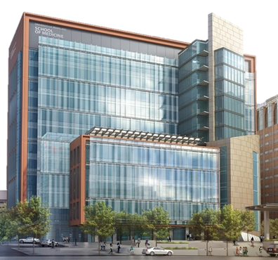
 Health Sciences Facility III is located in downtown Baltimore on the campus of University of Maryland, Baltimore, also known as UMB. This is a ten-story facility with a penthouse for mechanical equipment and two levels in the basement. All floors accommodate a host of offices, lab spaces, and various conference rooms. Most of the lab spaces have an open layout to promote collaboration among students and professors. The offices are mainly along the south wall to take advantage of the direct sunlight into the space. Within the basement there are special lab spaces like an MRI suite as well as other MEP rooms. The fifth and sixth floors will be left as a core and shell space.
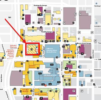
 The design of the envelope for HSF III includes 5 main elements: brick, precast, curtain wall, granite, and punched windows. The roofing system is a mixture of green roof and traditional IRMA roofing, as discussed in the next section. The brick façade located mainly on the east and west walls is intended to blend this building with the existing structures that embody UMB’s campus.
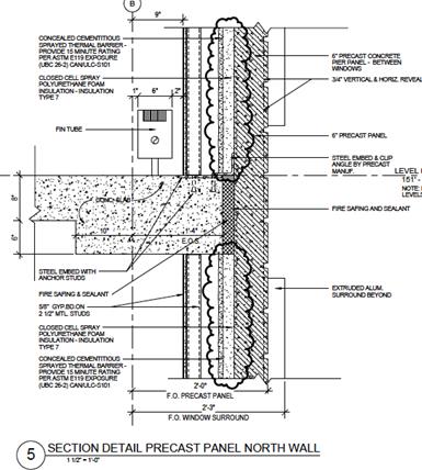
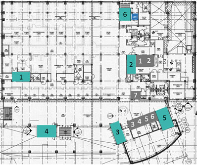 There are 6 elevators located in the building. Four of them serve as the main core, seen in the figure to the right. The two north elevators are the service elevators that access all floors, and the elevator in the southwest corner of the building only stops at the lower basement and the first floor. There are also stairs scattered throughout the building that service all of the floors. There is a difference in elevation at the north entrance of the building, which requires a small set of stairs as well as a wheelchair lift


Note: While great efforts have been taken to provide accurate and complete information on the pages of CPEP, please be aware that the information contained herewith is considered a work‐in progress for this thesis project. Modifications and changes related to the original building designs and construction methodologies for this senior thesis project are solely the interpretation of Kathryn Gonzales. Changes and discrepancies in no way imply that the original design contained errors or was flawed. Differing assumptions, code references, requirements, and methodologies have been incorporated into this thesis project; therefore, investigation results may vary from the original design.
This page was last updated on 2/28/2015 by Kathryn Gonzales and is hosted by the AE Department ©2015