
KATIE RITTER
STRUCTURAL OPTION
Contact Katie:
Building Statistics
Structural Systems:
FOUNDATIONS
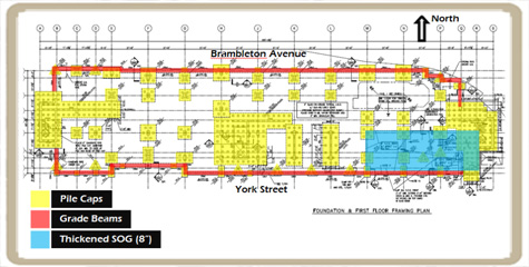
Located in a coastal area, the Residence Inn by Marriott site requires a foundation comprised of friction piles because of the high water table and lack of a firm bearing stratum with highly compressible soils present. Therefore, the hotel utilizes high capacity (100 ton) 12” square precast, pre-stressed concrete piles, driven to depths between 60’ and 70’. Clusters of piles are joined together by reinforced concrete pile caps, the largest of which are located in areas supporting shear walls above. Depths of pile caps range from 1’-4” at a perimeter column to 5’-8” at the shear walls near the elevator core central to the building.
A continuous reinforced concrete grade beam ranging in size from 24”x24” to 24”x40” is utilized around the perimeter of the building to transfer loads from the walls into the piles. A 5” concrete slab on grade reinforced with welded wire fabric is typical of the first floor, except where additional support is required for mechanical and service areas. Here, an 8” reinforced concrete slab on grade is required.
MAIN STRUCTURE – GRAVITY RESISTANCE
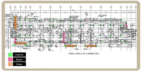
The Residence Inn by Marriott utilizes an economical 8” two-way flat-plate concrete floor system on all floors including the roof, with a typical bay spacing of 21’-6”, and a maximum span of 22’-0”.
Reinforced concrete columns, ranging in size from 12”x24” on the upper floors to 20”x30” at the first floor, support the two-way slab system. While the Residence Inn by Marriott is primarily a flat-plate system, a few specific areas on each floor utilize 12”x16” reinforced concrete beams to support the slab near openings. Along the exterior where the two-way slab ends at columns without a cantilever, drops are necessary to resist additional stresses due to the lack of structural continuity.
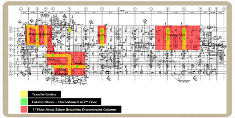
At the second floor, reinforced concrete transfer girders are employed to discontinue columns on the first floor, where they are undesired near the open lobby, meeting room, breakfast buffet, and indoor pool areas. The sizes of these vary, the largest of which is 72” wide and 54” deep. The large depth of these girders is permissible since the first floor has a height of 19’-0”.
Located between the first and second floors, the mechanical mezzanine level provides additional floor area for mechanical equipment. Due to the heavier loads anticipated by such equipment, an 8” one-way flat plate floor system with beams is used here. The maximum span is 21’-6” between frames and 14’-8” in the direction of the one-way slab span. Reinforced concrete beams typically 18” deep support the slab and transfer loads into the columns.
LATERAL FORCE RESISTANCE
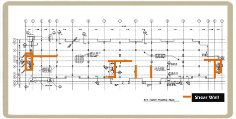
The Residence Inn by Marriott employs cast-in-place reinforced concrete shear walls to resist lateral forces. There are a total of fourteen shear walls, between 1’-0” and 1’-2” thick, and oriented in such a way to resist forces in both directions. These shear walls are continuous from the foundation to the top of the building, and behave as fixed cantilevers. They surround both the East and West stairwells, as well as the elevator shaft central to the building. Shear walls can also be found in between these areas to provide additional support. There are more shear walls oriented from North – South, which resist an overturning moment in the more susceptible direction. Lateral loads are transmitted to the shear walls through the floor diaphragms.
SPECIALIZED STRUCTURAL SYSTEMS
Canopies are located near each lobby entrance; one to the North along the Brambleton Avenue elevation, and the other to the South, along the York Street elevation. Moment connections are utilized to cantilever the canopies up to 10’ beyond the building structure, tying into the first floor columns. Each canopy is supported with steel wide flange framing. Typical sizes include W10x26, W16x40, W16x57, and larger varied sizes at the center supports of each canopy. The York Street canopy has steel hanger rods that are attached just below the fourth floor to provide additional support for the longer cantilever length.
The West stairwell requires special attention to support its three-story expanse of curtain wall. Steel HSS6x6 beams and columns transfer loads down to a cast-in-place concrete load-bearing wall at the seventh floor.
Curtain walls located in the guest rooms on the eighth and ninth floors span a smaller distance vertically, and therefore, additional framing is not required. The slabs above and below provide the anchoring points for this system.