|
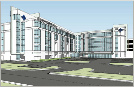
St. Joseph’s Women’s Hospital Neonatal Intensive Care Unit (NICU) 3030 West Dr. Martin Luther King, Jr. Blvd Tampa, FL 33607
|
|
Dennis Gibson — Construction Management |
|
This page was last updated on October 10, 2010, by DJ Gibson and is hosted by the AE Department ©2010. |
|
User Note: While great efforts have been taken to provide accurate and complete information on the pages of CPEP, please be aware that the information contained herewith is considered a work‐in progress for this thesis project. Modifications and changes related to the original building designs and construction methodologies for this senior thesis project are solely the interpretation of DJ Gibson. Changes and discrepancies in no way imply that the original design contained errors or was flawed. Differing assumptions, code references, requirements, and methodologies have been incorporated into this thesis project; therefore, investigation results may vary from the original design. |
|
Building Statistics Part Two... |
|
Superstructure The new NICU tower will be composed of a structural concrete superstructure. The main load bearing elements will be cast-in-place columns, and a cast-in-place two-way flat plate slab. This system was likely chosen to minimize floor-to-floor height while maximizing above ceiling space. Due to FAA restrictions, there were several permitting issues that were found when evaluating the overall building height during the design development phase. The design called for the building to be approximately three feet taller than FAA restrictions would allow, due to the proximity of the hospital to Tampa International Airport. This concrete superstructure allows for more above ceiling space for the extensive MEP systems, when compared with a structural steel system.
|
|
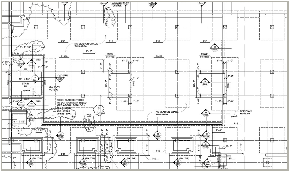
Figure 1. S2-11 from 100% CD’s. Compliments HKS, Inc. |
|
Although concrete dominates the design, the sixth floor penthouse provides a good opportunity to use lighter steel framing instead of concrete. Particularly because the mechanical penthouse is significantly smaller than the roof itself, about one-third the total building footprint, it would be superfluous to increase dead loads on the rest of the structure by using more concrete columns. Instead, W16 beams are framed into the steel columns that are anchored at the Level 5 Elevation (T.O. main roof). The simple structure is laterally supported by a semi-moment frame, where only a few W21 beams and girders have moment connections. The decking above is an 18 GA. composite metal deck with shear studs embedded in 7” of 4,000psi f’c concrete reinforced with W4.0 WWF. Some other areas of the building offer some HSS or other steel framing, but these are mainly in regions such as the main entrance, where an external canopy is to be installed, or some Phase 3 work where the old structure must be retrofitted into the new structure. |
|
Mechanical System The mechanical system will be partially tied-into the existing chillers and cooling towers on the current Women’s Hospital. However, there are provisions to demolish one chiller, provide two new ones, along with an additional cooling tower. There will be a total of eight new air handler units in the main NICU tower, four cooling towers, four chillers, and two boilers. It will be an air and water system, with fan coil reheat units in each zone for control. The main mechanical room for the new NICU tower will be located on the 6th Floor Roof. All new direct digital controls will be installed, and linked into the Building Management System, giving specific feedback to any web based PC on energy management requirements, archived trends, and LEED Data. Energy recovery units will be added to the bed tower’s AHUs, due to the extreme cooling loads that are associated with the Tampa region. This will play a part in the LEED Certification process as well, accounting for some of the Optimizing Energy Performance Credits under the Energy & Atmosphere section. Currently the projection is for a total of 14% energy use reduction for the new NICU tower and 7% in the existing hospital. Above ceiling plenum systems will bring return air to the ERV’s after which it will be exhausted. The layout of the Mechanical Penthouse can be found below in Figure 4, outlined in orange. Due to the nature of the hospital, and the stringent requirements on indoor air quality, MERV 17 filters will be used in all AHU’s. Although these filters are for permanent use in the system, there will be a brief time where the mechanical system will be running during construction activities. In this event, the ICRA document provides extra provisions for pre-filtering air that is going into the system. This is not a HEPA type filter, but instead is designed to provide general filtration of larger dust particles, and construction debris that may be in the vicinity of the AHU intake.
|
|
Electrical System As with all hospitals there is a need for redundancy within the system. Electrical power must not be interrupted, especially in an intensive-care unit. A few years ago, the entire electrical switchgear, UPS, and emergency generator system had been upgraded. This project included provisions for extra switchgears, in case the current project was to happen. Essentially all new construction for this project will be downstream from the switchgears which are already in place. The two generators that will be tied into the new system produce 1.5MW each and are accompanied by bypass isolation type automatic transfer switches. The main emergency switchgear is a 6000A system, while the normal system consists of two 2000A switchgears. Additional 1200A switchgears can be found in the chiller room and will power the chillers and cooling towers. |
|
Typical columns will be 24” x 24” reinforced 5,000psi f’c concrete square columns, placed along five column lines in the main NICU tower. These columns will extend up to the roof. The foundation consists of 4,000psi f’c concrete grade beams and spread footings that are occasionally shared by two columns. This can be seen in Figure 1 to the left, which portrays the structural drawing for the North side First Floor of the new NICU tower. Tandem spread footings can be seen highlighted in blue. To provide lateral support, seventeen 6,000psi f’c concrete shear walls have been placed throughout the structure. Six of these can be seen highlighted in red in Figure 1 to the left. These walls extend from the foundation all the way to the 6th floor roof. In several cases, the opportunity was taken to use the elevator and stair shaft walls to discreetly place shear walls, while still minimizing loss of open floor space. While the flat plate slabs are typically 12” thick reinforced with #5 and 6 bars top and bottom, there are some areas that required additional floor thickness, typically in the bathrooms. Since there is a need for a 2” recession in the slab for finishes, yet still a large dead load, the thickness is bumped up to 14” with #6 and 7 bars reinforcing these areas. |
|
Lighting System There is a very wide variety of lighting and fixture types in the St. Joseph’s Women's Hospital, however, most of the lights in the NICU tower will be fluorescent type, typically with indirect fixtures. T5 high output lamps are the most commonly used lamp type, and are used in a wide variety of applications. There are some instances of ceramic metal halide and LED lighting, which tend to be installed as accented downlighting. There are additional instances of high intensity discharge lighting, and also pendant type fixture in workstation areas. In some cases, incandescent lights are used to induce a warm feeling in patient rooms, where prolonged exposure to fluorescent lights may have a negative effect on patient mood. |
|
Additional Engineering and Engineering Support Systems Additional plumbing systems include med gases, such as oxygen, vacuum, and compressed air, along with pneumatic transfer tube systems to accommodate materials to and from nurse’s stations, surgical suites, and the pharmacy. The oxygen, vacuum, and compressed air will be tied into the existing system in the main part of the hospital. The fire suppression system will be a wet type sprinkler system, and two additional pumps will be installed to service the new NICU tower. Two electric traction elevators will be installed, which will have an industrial rating and sufficient space to accommodate a hospital bed. Additional communication features include nurse’s call stations, and hospital wide coding alerts. All IT data is linked into an uninterruptible power system to prevent the loss of data from instantaneous loss of power.
|
|
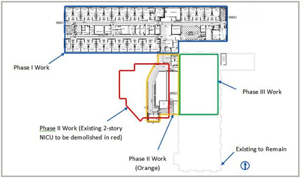
Construction St. Joseph’s Hospital is located in downtown Tampa, and is the largest hospital network in the Western Florida region. The St. Joseph's NICU project has been organized in three phases. The first will construct the new NICU tower. The second will involve moving all the patients and administration into the new tower, demolishing the existing tower, and completing the West Wing tie in to the existing structure. The third phase will include some renovation work in the existing building, focused mainly on facilitating the tie-in between the two buildings. Figure 2 below shows a general phasing diagram of the project. |
|
Figure 2. . Basic Phasing Plan. ALS-51A from 100% CD’s, Compliments of HKS, Inc. |
|
The work on the superstructure of the main NICU tower will utilize a concrete table forming method. The forms are erected once, then simply lifted from floor to floor with a crane to begin the next pour. This was An important decision by the project team, that is allowing them to meet the critical Phase II turnover deadline that the owner is expecting. An additional challenge is the lack of site space for staging and even cranes to set up. Although there is a significant amount of space to queue deliveries on local side streets, on site logistics will be very difficult as the footprint of the building does not allow for much else. The majority of MEP systems are however tied into existing systems in the hospital. This helps with cost because the equipment is already there, but creates a challenge in actually tying in these systems. Often times limited access and asbestos can make this a very difficult task. Careful planning and preparation will need to occur, and cannot interrupt daily operations. Avoiding clashes between the hospital operations and the construction activities may be the most important determinant of success on the project. Things like egress, noise, vibration, dust, and access to existing employee parking will need to be of primary concern throughout the project. |