
|
|
|
Zachary Haupt—Mechanical Option |
|
McDonogh School Campus Green Project |
|
Owings Mills, MD |
|
This page was last updated on October 11, 2010, by Zachary Haupt and is hosted by the AE Department © 2010. |
|
Note: While great efforts have been taken to provide accurate and complete information on the pages of CPEP, please be aware that the information contained herewith is considered a work-in-progress for this thesis project. Modifications and changes related to the original building designs and construction methodologies for this senior thesis project are solely the interpretation of Zachary Haupt. Changes and discrepancies in no way imply that the original design contained errors or was flawed. Differing assumptions, code references, requirements, and methodologies have been incorporated into this thesis project; therefore, investigation results may vary from the original design. |

|
Building Statistics |
|
Primary Project Team: - Owner: McDonogh School - Architect: Bowie Gridley Architects - Civil Engineer: Matis Warfield - MEP Engineer: James Posey Associates, Inc - Structural Engineer: Linton Engineers, LLC - Landscape Architect: Brian J. Stephenson + Company - Food Service: HMC, Inc. |
|
Part I
Building Name: McDonogh School Campus Green Project
Location: 8600 McDonogh Road Owings Mills Maryland, 21117
Building Occupant Name: McDonogh School
Occupancy: K-12 boarding school
Size: 68,000 SF
Number of Stories: 3 stories
Dates of Construction: Completed and operational date: September 2012
Actual Cost Information: Total project budget $16,000,000
Project Delivery Method: Design-Bid-Build
Architecture:
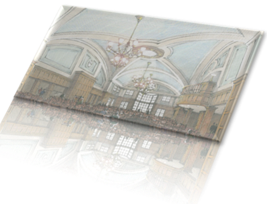
The Edward St. John Student Center is to become the hub of McDonogh campus. The student center will be tailored with a 3 story lobby/atrium that will require smoke exhaust, 15,000 SF dining hall, 6,000 SF commercial kitchen, 2,000 SF auditorium, 2,000 SF dance studio, a nurses sweet, and the remainder of the building is filled with classrooms that range from art and photo to general seminar. Flexible space throughout has been taken into consideration to accommodate meetings, lectures, and special events. The dining room interior is to be architecturally classic, having high ceilings and large windows, maximizing the amount of light being able to enter.
Major National Model Code: IBC 2009, IMC 2006, IEC 2006, IFC 2006
Zoning: Zoning is done by Baltimore County (Baltimore County Zoning Regulations) Use Group Educational E
Historical Requirements: Special considerations were taken into account to complement the surrounding buildings. The exterior facade was to match existing buildings by maintaining the same style of architecture.
Building Enclosure:
Building Facades: The exterior walls are to be constructed using veneer brick with 2” of air, 2” of rigid insulation followed by an air barrier, 1/2” sheathing, 6” metal stud, batt insulation (R-19), and 5/8” gypsum wallboard. Roofing: There will be two roofing systems used, one for the sloped roofs and one for the flat roofs. The sloped roofing system is to be an arched metal roof tailored with ice and water shield, arched 5” rigid insulation, and 1 1/2” roof deck. The flat roof will be made up of SBS multi-ply modified bitumen roof membrane, cover board insulation, thermal insulation, and roof deck. The entire roofing system is to be supported by a concrete slab.
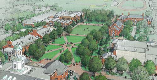
Sustainability Features: 3 story lobby/atrium to allow maximum day lighting Building orientation carefully selected to provide a new green space on campus
Part II
Architecture: “The Edward St. John Student Center will become the hub of campus activity, with its dining, teaching, and meeting spaces as well as the infirmary and school store.” The project is being elegantly designed by Bowie Gridley Architects. The Student Center is a 3 story; 68,000 square foot building that will house a 3 story atrium, dining halls, dance studio, conference rooms, auditorium, and classrooms that range from art and photo to general seminar. Construction: The building delivery method selected was Design-Bid-Build. The Student Center is expected to be completed and operational by September 2012. Special considerations were taken into account to complement the surrounding buildings. Electrical: The Student Center will have both 480V-3 phase and 120V-1 phase service to energize the building. An emergency generator will serve multiple buildings on the McDonough campus including the new Student Center. This generator will be utilized in order to prevent power loss for important systems such as; the smoke exhaust system located in the 3 story atrium, and other various lighting fixtures. Lighting: Every space found within the Student Center will have its own unique lighting fixture. Dining halls will receive large suspended fixtures, regular office spaces will have recessed fixtures, and conference rooms will have a variety of lighting fixtures with different control configurations. The lecture hall will have dimmable house lights combined with typical stage lighting. Most spaces are able to take advantage of the day lighting provided by the architect. Mechanical: The Student Center will have an HVAC system primarily comprised of multi-zone and single-zone VAV air handling units. There will be 5 single zone VAV air handing units, 1 single zone CV unit, and 2 multi-zone VAV units. One multi-zone VAV unit will cover the entire third floor, while the other covers the first and second floors. All of these units will receive chilled and heating water from a new central plant located on McDonough’s campus. A tertiary pumping system will be utilized for distribution within the building to AHUs and miscellaneous heating equipment. The total connected cooling load from the Student Center’s HVAC system is approximately 400 tons, while the total connected heating load is 3300 MBH. The system will be designed by taking load diversity into consideration. Structural: The overall structural system is an all concrete building with self-supporting 2-way slabs. Concrete beams and columns are used in order to support the longer spans. The building sits on 12” thick footers connected to a 4” normal weight concrete slab on grade. The concrete beams vary in size; however the most common size is a 20”x20” beam. In an effort to decrease size of the concrete beams, supplemental steel was implemented. Custom made, prefabricated light gauge steel trusses top the building in order to support the roofs and attic spaces.
|