What we're Doing
![]()
What we're Doing
|
|
| This page contains everything we have done over the period of the semester. It has number pictures of drawings of Old Main. It contains links to each of our presentations. Any concerns for production plans, process plans, and tooling and fixturing are contained in the presentations.
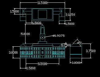
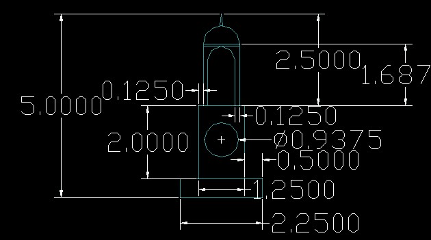
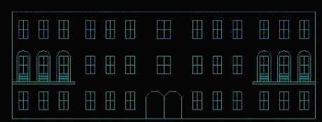
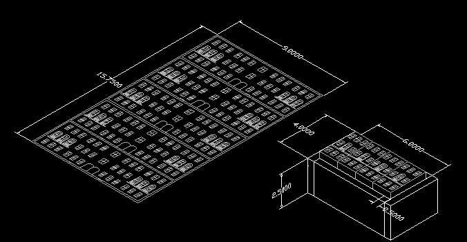
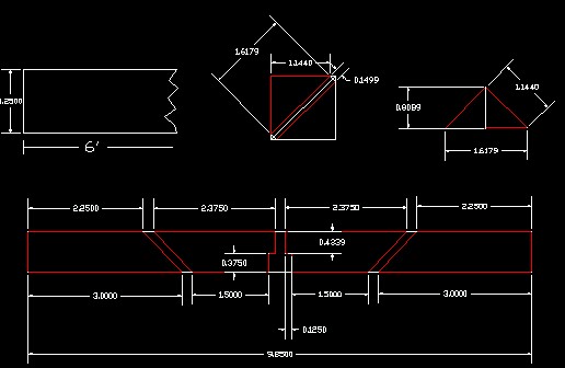
PicturesThe Total Old Main Redesign with dimensions: Here is a Link to the AutoCAD file. This file contains all the new dimensions for the Old Main and contains other dimensioned parts as well.
Method of Manufacture:
This is what the fixture will look like for the front and sides:
Here is a Brief Description of the Process Procedure for manufacturingProcedure: To produce the front face, we cut a piece of 9” x 15.5” x 0.125” thick aluminum sheet. We will place this plate into a vacuum fixture. Because there was no vacuum fixture, each front face was done individually, but the tooling and procedure does not change, only the number of faces produced at a time. The plate was face milled, using a 3” face mill to produce the effects of the lines. The windows were created using a ¾” spot drill, and the effects around the windows were created using a 1/16” ball mill. The side faces were placed into a box fixture, large enough to hold four of these 3” x 1.5” sections of 0.125” thick box tubing. This is enough to accommodate two Old Mains. The sections were face milled, using a 3” face mill to create the line, then the windows were produced with a ¾” spot drill and the effects around the windows were created using a 1/16” ball mill. The grooves in the side were created using a 1/8” end mill; these grooves are for attachment. The flat part of the roof was manufactured in two parts: the bottom plate and the top plate. The top plate consists of cutting a 21.875” x 0.5” thick piece of aluminum to 2.625” sections. To maintain dimensions, the plate was face milled, using a 3” face mill on each side; this also helps produce a good finish. The bottom plate was manufactured by machining a 22.375” x 3.125” x 0.5” thick piece of aluminum. One of the sides was face milled, using a 3” face mill for a good finish. The other side included face milling the surface, using a 3” face mill. Then, using a 1” end mill to create the over hang. A ½” spot drill was used to create the diagonal effects; finally, a 5/16” end mill was used to create the holes for the column insertion. The triangular part of the tower was outsourced and cut to the dimensions that are desired. The tower was produced in three parts. The bottom and middle section were produced by fixturing them 45 degrees in the specialty jaws and end milling, using a ¼” end mill, the corners to create the flat sections. Then they were fixutured on parallels and the steps were end milled, using a ¼” end mill. For the middle section a hole for the clock was end milled, using a ¼” end mill. The top of the tower was created by, using a 1 ½” end mill to create the flats and a ¼” end mill to create the archway; rotate 45 degrees and end mill the flats, using a ¼” end mill, plus ball mill the columns. The contour of the dome was created in a lathe followed by a cutoff operation. The base was produced using a 1/8” end mill to create the slots for insertion of the front, back, and side plates and a 5/16” spot drill for the column insertion to the base. The columns were cut to size, then sanded and bead blasted to create the contrast effect.
Back to Top |
|
Copyright or other proprietary statement goes here.
|