

Neutron Radiography Measurements for Water Transpor in an Operating Polymer Electrolyte Fuel Cell
| Participants: | M. Mench, Professor of Mechanical Engineering |
| Jack S. Brenizer, Professor of Mechanical and Nuclear Engineering | |
| Kenan Ünlü, Professor of Mechanical and Nuclear Engineering | |
| N. Pekula, Graduate Student | |
| K. Heller, Graduate Student | |
| S. Çetiner, Graduate Student | |
| Services Provided: | Neutron Beam Laboratory |
| Sponsors: | General Motors Corporation |
| RSEC |
Introduction
Recently fuel cell technology has become of high interest for stationary and portable power supplies including automotive applications especially. The recent attention given to fuel cells has been stimulated by vast improvements in performance, increased environmental concern, as well as a need for petroleum-free power sources. The fuel cell type receiving the most interest of late is the polymer electrolyte fuel cell (PEFC) because of its high performance, mild operating conditions, simplicity, and rapid advances since the early 1990's. For these reasons, the PEFC has been chosen, among other uses, as the most suitable replacement for the internal-combustion engine for automotive power applications.
Although, there have been numerous mathematical models in literature that predict water production and transport phenomenon in fuel cells, there has been little success in its experimental investigation. Due to the metal housing of the fuel cell along with several of its components, neutron imaging is an attractive non-intrusive testing technique for the visualization and quantification of liquid water-reactant gas, two-phase flow within the cell. These processes yield great insight into the operation of the fuel cell pertaining to water management that can undoubtedly lead to improvements in cell performance and design.
Background
To maintain high operating performance, the fuel cell's electrolyte must be hydrated during operation to support ionic conductivity. It is common to use humidified reactant gas flows to supply the cell with appropriate amounts of water. In addition, due to the electrochemical reactions inherent to the PEFC, water is produced at the cathode of the fuel cell. However, excessive levels of water in the cell lead to a reduction in cell performance due to the obstruction of reactant gas transport. This phenomenon is referred to as flooding, and commonly occurs in the gas reactant flow channels of the cell. In addition, several water transport mechanisms exist within the PEFC, which add to the complexity of water management during operation. Therefore, there is extensive research currently ongoing industry-wide to better understand water management issues in PEFCs to improve the overall performance of the fuel cell and its design.
The membrane-electrode assembly (MEA) consists of the fuel cell's electrolyte, electrochemical reaction sites, and the gas diffusion layers (GDLs). The GDLs supply the reactant gases from the adjacent flow channels to the reaction sites. It is within this assembly and the gas flow channels that all the cell's water production and transport occurs. However, this portion of the cell is surrounded by several components comprised of aluminum and graphite including flow field plates, backing plates and current collectors (see Figure 1). Therefore, visualization of water transport within PEFCs has been extremely limited, especially that in which typical cell operation and performance has been maintained. The significant differences in neutron attenuation characteristics of hydrogenous materials and aluminum or carbon however allow for neutron imaging techniques to produce a non-intrusive visualization procedure of the two-phase flow (liquid water and reactant gas) within the cell. Neutron radiography and radioscopy in the through-plane direction of the cell, with respect to the cell's backing plates, yield adequate spatial resolution for discerning liquid water in the flow channels of the fuel cell. In addition, radiographic image analysis at the Penn State Breazealle Nuclear Reactor's (PSBR) Neutron Beam Laboratory allows for the mass and volume of liquid water within an operating fuel cell to be quantified.
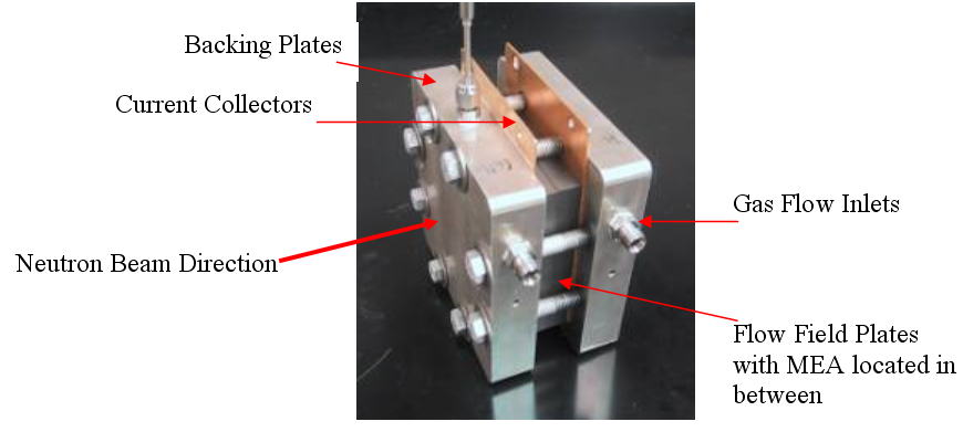
Figure 1: Assembled PEFC
Fuel Cell Test Setup
An integrated fuel cell testing station at the PSU Neutron Beam Laboratory was constructed in order to control and monitor the operating parameters a PEFC while neutron imaging was conducted. The user-friendly Neutron Beam Laboratory Test Station (NBLTS) was designed and installed so that it was isolated from the neutron beam source, protecting the operator and station components from radiation poisoning and contamination. The station can accommodate various sized hydrogen-gas fuelled PEFCs for neutron imaging processes while the following conditions are controlled by the operator on the station's control panel. Figure 2 illustrates the NBLTS layout.
• Gas flow rates
• Inlet gas temperature and humidity
• Cell temperature
• Current/Voltage draw
• Operating pressure
• Nitrogen purge
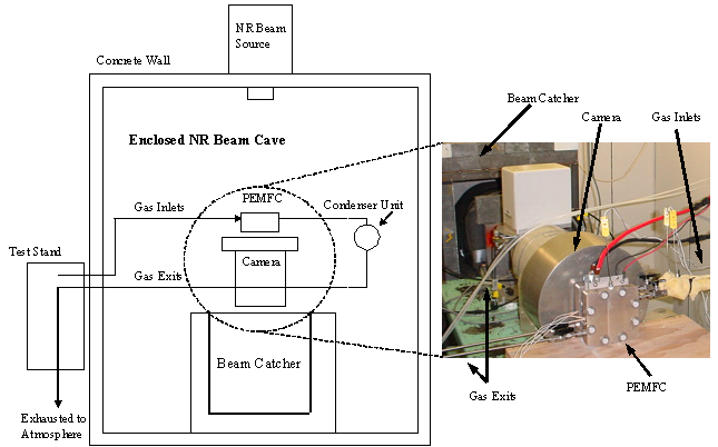
Figure 2: NBLTS Layout
Fuel Cell Design Optimized for Neutron Imaging
A 50 cm 2 PEFC is used for evaluation with the NBLTS. Aluminum flow field plates replaced more commonly used graphite plates due to lower material neutron attenuation characteristics. The aluminum plates were thinly coated with gold to increase their electrical conductivity (pictured in Figure 3) to maintain high cell performance. The thickness of the each plate was reduced to 0.25 in. to reduce neutron attenuation and scattering. The thickness of the aluminum backing plates was also reduced from a total thickness of 2 in. to 1.3125 in. In addition, the typical copper current collectors were switched with aluminum replacements.
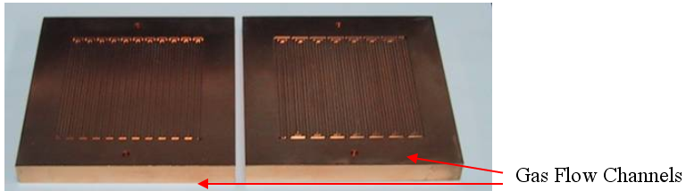
Figure 3: Gold-coated Aluminum Flow Field Plates
Neutron Radiography for Fuel Cell Applications
The high spatial resolution associated with neutron radiography allows for excellent visualization of liquid accumulation in the PEFCs. Figure 4 below illustrates a radiographic exposure of the operating fuel cell at the specified operating conditions. The exposure time of the radiograph was approximately 4 minutes at a reactor power level of 800kW.
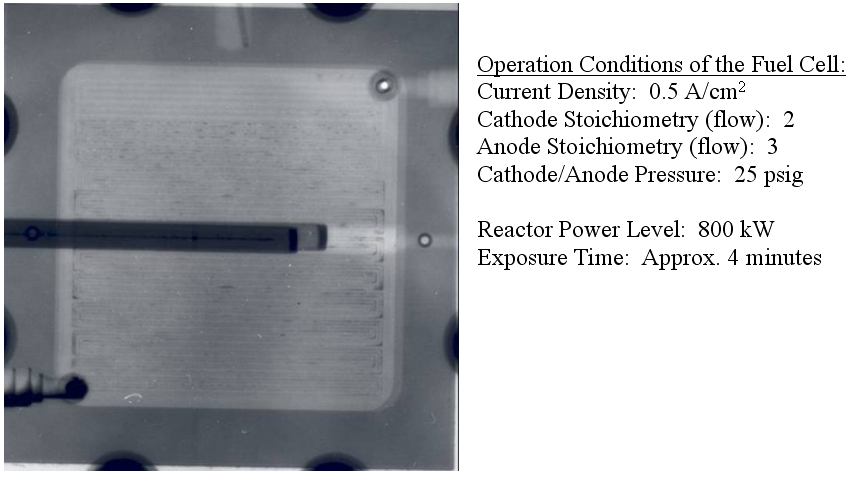
Figure 4: Radiographic Image of Operating PEFC
The accumulation of liquid water in the flow channels of both the anode and cathode is visible. It is typical for an abundance of liquid water to accumulate at the 180º turns of the flow channels due to changes in flow pressure and momentum. The geometry of the channels at these locations may also aid in the accumulation of liquid water. By momentarily increasing the hydrogen gas flow rate, it was concluded that a significant amount of the total visible water in the cell was located in the flow channels of the anode.
Neutron Radioscopy for Fuel Cell Applications
To achieve a maximum neutron beam flux, the reactor is operated at 1 MW power for all fuel cell radioscopy experiments. The spatial resolution pertaining to the applied magnitude level is approximately 225 microns per pixel. Figure 5 illustrates two-phase flow within the flow channels of the fuel cell, where he darker shaded areas depict liquid water. The temperature of the fuel cell for this example was approximately 30 ° C where liquid water condensation in the cell is quite abundant.
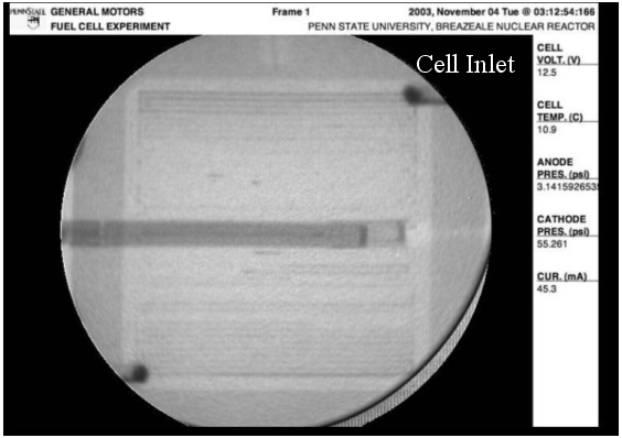
Figure 5: Radioscopic Image of Two-phase flow in an operating PEFC
The digital sampling rate of 15 frames per second for radioscopy experiments proves sufficient for all transient processes of the fuel cell including determining the velocity of moving water droplets. In addition, the accumulation and purging cycles of water inside the cell is easily attainable through real-time radioscopy. Initial results have seen a direct correlation between the time scales of these cycles and the cell's operating conditions, most notably gas flow rates.
The ability to store individual radioscopic images digitally allows for easy post-process image analysis including ascertaining pixel intensity values within the fuel cell versus real time. Consequently, the determination of water volume within the cell as a function of time is attainable by referencing a pre-generated calibration curve. This curve is generated using a water-filled wedge constructed of aluminum and other materials similar to the fuel cell. It has the exact same through-plane dimensions to duplicate the neutron attenuation and scattering effect of the fuel cell. Seen in Figure 6, the wedge contains a water filled void of known varying thickness. The steady and gradual increase in pixel shade from the bottom to top of the wedge is representative of the increasing water thickness level within the wedge. Through radioscopy of the wedge, pixel intensity values are recorded at known water thickness levels producing a calibration curve. This curve can then be referenced to assign water thickness values to individual areas within
the cell or the entire cell as a whole. A calibration curve must be generated for each experiment to account for inconsistencies in the neutron beam flux and reactor power level.
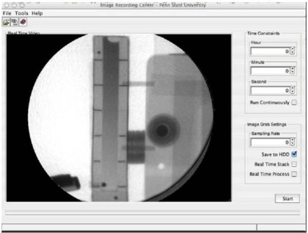
Figure 6: Water-filled Calibration Wedge
Figure 6 also illustrates the user-friendly interface that was created for fuel cell radioscopy experiments. The length of testing and sampling rate is easily programmable.
Several post-process image enhancement techniques were established to increase the overall radioscopic image quality and accuracy of the water quantification process. Minor fluctuations in the reactor power level which is common during testing result in changes in pixel intensity values. This causes an error by giving the allusion of varying water levels. By monitoring a reference location on each image, the fluctuation of the beam is determined and the entire pixel matrix of the image is normalized accordingly. The reference is a static location such as the backing plate outside the active area where pixel intensity should be constant throughout the length of the test. In addition, the intensity of the neutron beam is not perfectly uniform across the image resulting in different values of pixel intensity even where material attenuation characteristics and thickness are identical. This also leads to errors in water quantification. By examining a blank image (only the uninterrupted beam) the average pixel intensity value is determined. The acquired average value is divided by each pixel value of the blank image to produce a corresponding correction factor for each pixel. The correction factor matrix is multiplied by each image recorded during actual experiments to produce a flattened image making the initial beam intensity uniform. Lastly, random noise and noise caused by the analog to digital conversion process can cause time varying error. The pixel intensity values of each image along with the next three frames are averaged together. This process improves image quality and makes liquid water accumulation and movement more discernible.
Ongoing Work
Currently, there are efforts to ensure the accuracy of the water-filled wedge calibration curve by comparing the results generated by the curve to a known water thickness. Data collection is also presently being performed for a wide range of fuel cell operating conditions. The cell's total water volume content versus time is of high interest as well as water volume at individual locations within the cell. Initial results have shown distinct time scales for the accumulation and purging periods of liquid water during fuel cell operation. Continued analysis includes investigating the relationship between these periods and various operating parameters. Liquid water droplet characteristics are also being examined including the velocity of droplets in the gas flow channels. In addition, the critical volume of the droplet in which movement initiates is measured as well as its effect on other stationary droplets. The reactant gas flow pressures, operating temperatures, and cell performance are measured and monitored in real time for each experiment.
Conclusions
Neutron imaging has proven a successful non-intrusive process to visualize two-phase flow inside a polymer electrolyte fuel cell. The spatial resolution provided at the Penn State Nuclear Reactor Neutron Beam Laboratory yields excellent imaging of liquid water inside the gas flow channels of the fuel cell. Neutron radioscopy with a temporal resolution of 15 frames per second, is capable of visualizing and quantifying all the transient processes associated with operation. Preliminary results have shown quantification of water volume and water transport is attainable through these processes. Continued research will aid in better understanding of water management issues in PEFCs and ultimately lead to improved performance and cell design.