James D. Rotunno
|
Butler Health System |
Home
|
|
|||||||||||||||||||||||||||||||||||||||||||||||
| Note: While great efforts have been taken to provide accurate and complete information on the pages of CPEP, please be aware that the information contained herewith is considered a work‐in‐progress for this thesis project. Modifications and changes related to the original building designs and construction methodologies for this senior thesis project are solely the interpretation of Jim Rotunno. Changes and discrepancies in no way imply that the original design contained errors or was flawed. Differing assumptions, code references, requirements, and methodologies have been incorporated into this thesis project; therefore, investigation results may vary from the original design. | ||||||||||||||||||||||||||||||||||||||||||||||||
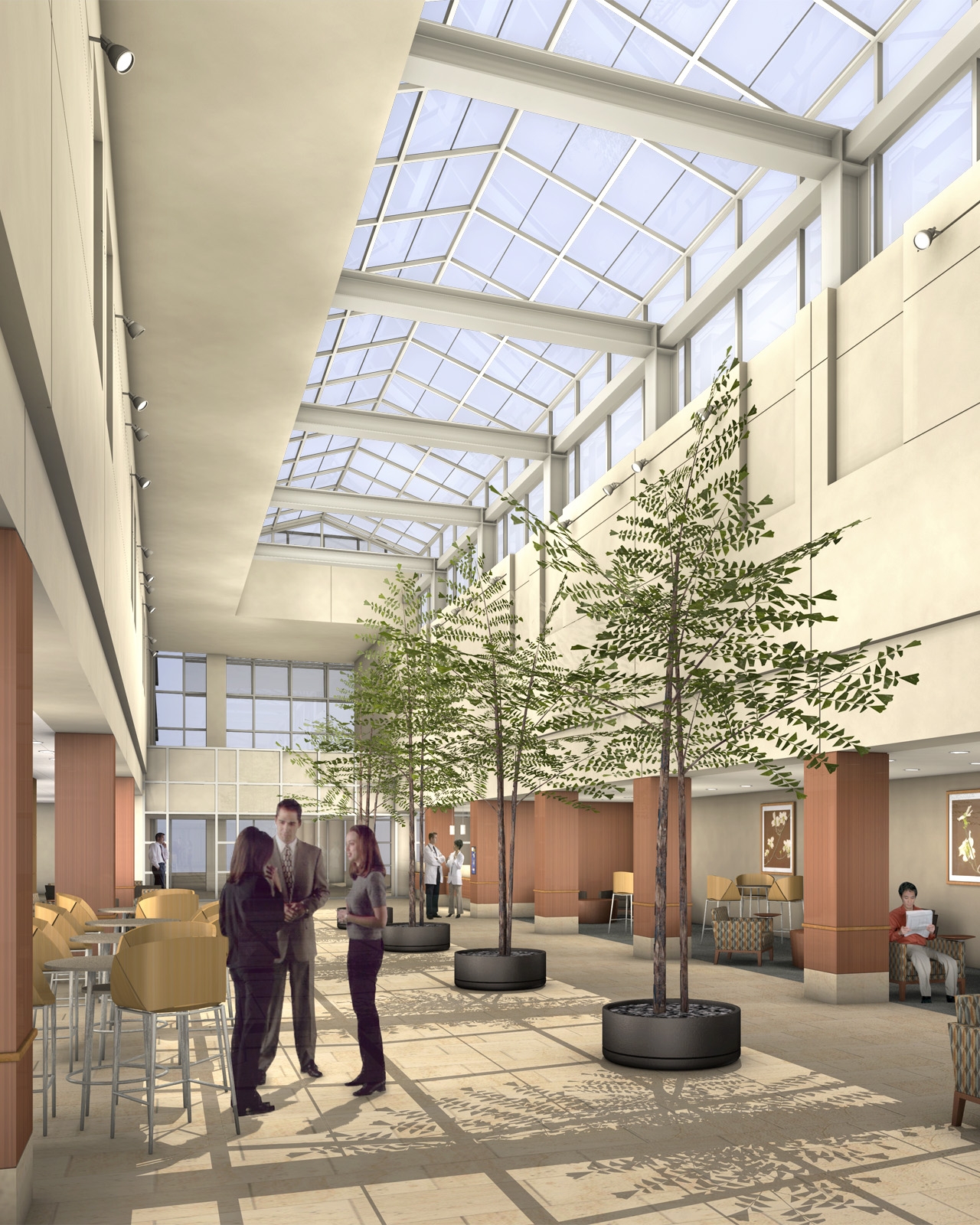
Sustainability Concepts: The design of the large glass atrium area extending up two levels from the second floor in the main reception and waiting areas provides natural daylighting that extends deep into that level. |
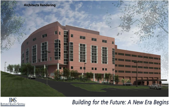
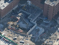
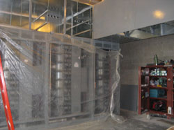
Architectural Features: The architectural form of the building on the North side reflects the contour of the topography with the stepped walking path, and the curvature of the roadway with respect to the arcing wall of the North facade. Each level of the new addition has specific functions with the Ground and first floor levels being devoted to emergency generators, elevator pits, mechanical, electrical, boiler, chiller and storage rooms as well as some staff support areas. One quarter of the second floor area is given to training rooms, while approximately another quarter is seating / waiting areas; and the balance is given to an auditorium, chapel, physician lounges, a boardroom and conference rooms. Third floor space is devoted to the Ambulatory Care Unit, operating rooms and outpatient surgery. Fifth floor space is the Critical Care Unit and its support facilities. Floors six and seven are patient recovery rooms. On the top level of the structure is the penthouse level which houses the air handling units and mechanicals. |
Building Enclosures: Wall systems are primarily composed of a brick veneer with an air space on two inch polisocyanurate rigid insulation attached to 6”structural metal studs sheathed on both sides with 5/8” gypsum wall board and filled with 6” batt insulation. Glazing systems for the exterior walls are a glazed aluminum curtain wall system manufactured by Wausau and utilizing the Wausau “2-1/2 Inch Face Superwall/Pressure Wall Series”. Sealed insulating glass units are primarily 1” tinted insulating glass: ¼” tinted exterior light equal to PPG Gray with a low “E” coating matching Viracon VE3-2M on surface #2, 1/2 inch air space, ¼ inch clear interior light. Heat strengthened both lights. |
 |
Applicable Building Codes: |
Zoning: City of Butler Zoning Regulations 1-2 Hospital ( Non-separated mixed use) 1B (NFPA Type 2 (222)) No Building Floor Height Limitations |
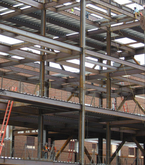 |
Structural System: The structural system for the building addition consists primarily of wide flange members for the beams and columns above ground level. Columns are mostly W14's ranging from 43 - 176 lb/ft. Beams have a wide range of sizes depending thier loading and span with the two most common sizes being W18x40 and W16x26. Floor systems are comprised of wide flange beams supporting composite metal decking and composite concrete floor slabs. Floor thicknesses are 6-1/2" total with 3-1/2" concrete 5" shear stud length and either 6x6 WWF or #4 and #5 deformed bars @12" O.C. |
|
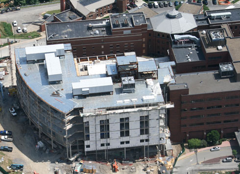
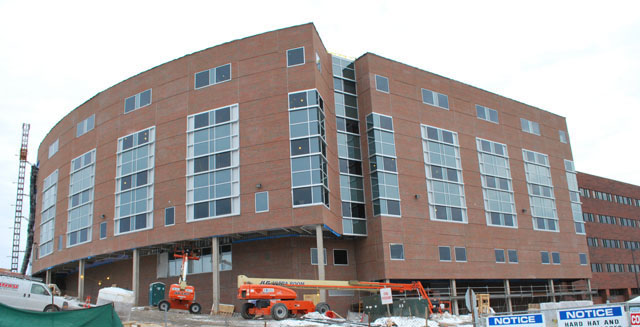
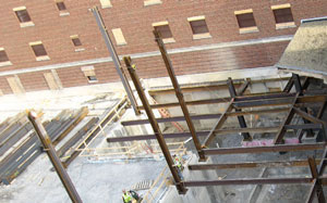
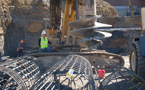
| Photos by Butler Health System | ||
 |
 |
 |
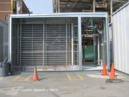
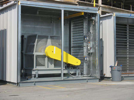
Mechanical Systems: Heating, ventilation and air conditioning (HVAC) requirements are being provided through the use of eight air handeling units (AHU's) at the roof top levels. AHUs 1,2&3 supply 62,000CFM each of conditioned air, while AHUs 4&5 supply 18,500, AHU 7 supplies 4000 and AHU 6&8 supply 4700CFM each. |
|
||
|
Fire Protection Systems: Spray-on fireproofing has been applied to all structural columns beams and load carrying HSS bracing members. |
||
 |
|||
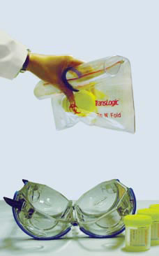
Special Systems: A pneumatic tube delivery system is used throughout the building to transport various items such as documents, medications or other light materials.The system is designed by Swisslog and is designed to meet the unique transport requirements of hospitals fast, accurate reliable and securely. |
Electrical: The power supply enters the structure from the existing building into the first level electrical room on the plan west side of the addition where it comes into the 2500kVA transformer which supplies power the building. The main and emergency electrical rooms have panelboards for both 208/120V and 480/277V 3 phase 4 wire feeds and panels. There is at least one electrical room located on every floor to supply both the high and low voltage needs for the lighting, equipement and general usage power requirements. Emergency backup power is supplied by a standby generator located on the ground level directly under the main electrical rooms. Lighting: Lighting requirements in a hospital setting vary widely and can be extremely critical in an operating and emergency room setting. |
||
 |
 |
||
Photos from Swisslog |
|||
Senior Thesis Main Page | The Pennsylvania State University | Architectural Engineering Department | AE Computer Labs Contact James Rotunno: jdr274@gmail.com |
This page was last updated on October 04, 2009, by Jim Rotunno and is hosted by the AE Department ©2010 |