Building Statistics part 1 |
|
|
|
| Owner: The Pennsylvania State University |
Architect: Crawford Architects |
Exterior Facade Consultant: Bohlin Cywinski Jackson |
|
|
|
| Construction Manager: M. A. Mortenson Company |
Structural Engineer: Thorton Tomasetti |
MEP Engineer: Moore Engineering Company |
|
| Landscape Architect: Lager Raabe Skafte |
|
|
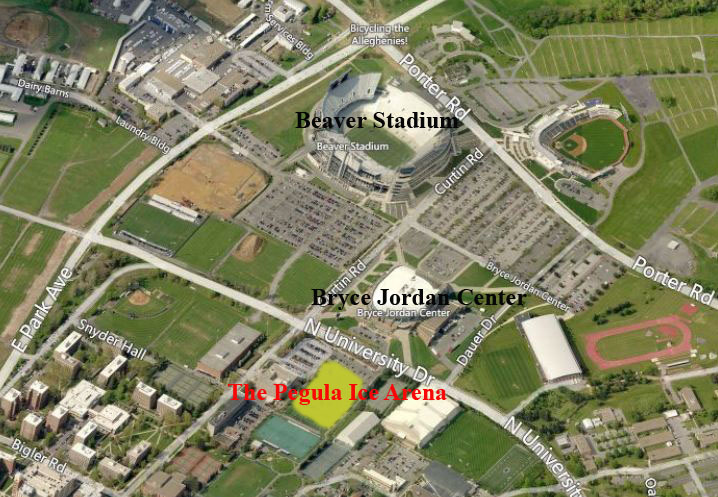
Figure 1 | Birds-eye view: Bing Maps |
The future site of the Pegula Ice arena can be seen in yellow above. This was formerly the Penn State Lacrosse Field, which was most recently relocated outside of the Multi-Sport Indoor Facility. This location was chosen due to it's vicinity to other sport complexes; most notably the Bryce Jordan Center and Beaver Stadium. Locating the Pegula Ice Arena adjacent to other sports facilities was important in part just to keep the sport complexes and their facilties close together; but also because no additional parking was designed to be added for the new ice arena. Therefore, the commuter lots located around Beaver Stadium and the Bryce Jordan Center will be used for the Pegula Ice Arena. |
The Pegula Ice Arena is primarily designed to house the future Penn State Nittany Lions Division 1 hockey team. It has a main arena with approximately 6000 seats for spectators. The building also has a community rink with approximately 300 spectator seats. The community rink will be open to the public 360 days a year equipped with a skate rental center. In addition to this; the building will have approximately 5000 sf. of strength and conditioning space; offices for the coaching staff, facility managers, and Penn State Intercollegiate Athletics offices; and a Tim Hortons restaurant on the main concourse. |
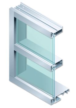
Wall Facade - The exterior wall will largely be composed of curtain wall with glazing and brick. The most significant portion of curtain wall encompasses the entire east facade of the building and is visible along University Drive. The curtain wall will rest on an aluminum track frame which will house low e-coated insulating glass. The glass will be ultraclear with each glass lite a 1/4" thick and a 1/2" air space between each lite. Additional to this, each glass panel, along the east facade, will be approximately 11' x 4'. Reference figure 2. The brick is similar to Penn State University's facade theme. It is a red brick tying into concrete masonry units. Finally the brick will be installed using a stretcher bond technique which can be seen in Figure 3.
Roof - The roof incorporates three different systems. A portion of the roof uses TPO membrane roofing. The TPO roofing system consists of a layer of fireproofing, vapor retarder, insulation board, and a final sheet layer of thermoplastic polyolefin (TPO). The TPO sheet was chosen because of its high reflective capabilities making it very energy efficient. The second system consists of insulated metal panels. The architect chose these to match some of the nearby existing conditions. Specifically, the Bryce Jordan Center, which can be seen directly east of the Pegula Ice Arena, incorporates similar metal panels into its building enclosure. Finally, there will be an equipment screen which is to hide the air handling units from the public eye. |
Building Statistics part 2 |
Mortenson Construction was awarded the guaranteed max price contract to build the Pegula Ice Arena. The delivery method is design bid build with CM at risk. The project cost, including design fees, is $102 million. The project started in February 2012, and needs to be commissioned and ready to open for the first puck drop on October 11th, 2013.
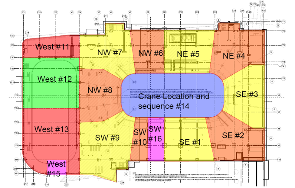
The project is sequenced in a counterclockwise fashion starting in the center portion of the building along the south. The crane was staged inside the ice rink. Steel was installed during normal work hours while the precast stadia was installed during the second shift. Truss erection required a second crane to coordinate tandem picking and this second crane was also able to assist with some of mechanical units that needed picked onto the roof.
The figure below represents the steel sequencing for the building. This is largely the sequence that every trade approached this project with as well.
|
The structural steel consists of a braced frame with some moment connections located where girders tie into columns. There are W beams and columns located throughout the entire building. The roof consists of a combination of metal joists and trusses. Located on the south and north, of main rink, are roof joists as well as on the western side over the community rink. Over the main rink, there are to be trusses that span the width of the ice and seats. These trusses are being assembled in pieces. There are steel rakers that support the precast stadia, which are where the seats are located. Finally there are HSS columns located on the east curtain wall, facing University Drive, that were placed for aesthetic purposes.
The precast stadia includes two concrete mix designs. These include a 6000 psi mix for the main concourse stadia and an 8000 psi mix for the event level stadia. The stadia is primarily reinforced using pre-stressed deformed billet-steel bars. The rakers, supporting the main concourse stadia, have a rigid base with a braced frame connecting to the main concourse floor level. The tub connections cantilever out from the event level and therefore have a moment connection.
The floor systems are composed of composite steel decking with an average thickness of six inches. The floor systems primarily utilizes #4 and #5 bar reinforcing with a top clear cover of ¾”. Shear studs are also utilized throughout the system. The event level is is going to be all exposed concrete at the summation of the project which is why a water cure was required along this floor. This along with other construction means helped reduce the amount of concrete during curing.
A typical steel column used within the building is a W24. The columns that extended the majority of the buildings elevations are typically spliced above the event level floor which allowed for continued work of the beams and girders supporting the event level floor. This building is very atypical in size but a somewhat typical section is approximately 32’ by 32’ with W18x35 beams supporting the floor. Finally the trusses supporting the main rink ceiling extend nearly 200’ in length and reach approximately 13 feet in depth. They are fabricated and delivered in three different sections and are composed of W14x34, W14x43, and chords in between these W flanges. |
There are four main sources of fuel supplied to the Pegula Ice Arena. In order to heat the building a steam line is connected from a central plant located on the Pennsylvania State University’s campus. The cooling for the building is a chiller also supplied form a central plant on campus. Finally hot water is also supplied from a central plant located on campus.
There are 12, custom designed, air handling units supporting the building. All of the systems use 25% ethylene glycol. This is used as a cooling and heat transfer liquid to better optimize the system and subsequently save energy. Four of the AHU’s service only as dehumidification units. One supports the team lockers and weight room, one supports the community rink, and the other two service the main competition rink. The other eight support heating and cooling services: six contain economizers, while two utilize a total energy recovery wheel.
There are multiple pumps and heat exchangers located within the building. The reason hot water is serviced into the building is to support the radiant heating system located in the building. This system rests along a drink rail next to the glass façade along the eastern curtain wall. |
The majority of the lighting contained within the building is of the compact fluorescent nature. These lights are in all corridors and most offices. Located at the community rink are fluorescent high bay surface fixtures. The main competition rink utilizes ellipsoidal aisle fixtures with high performance lamps (HPL). Lastly LED down lights are located throughout the parking lot.
There are three transformers located at the north-west corner of the building. Two service the building, while one primarily serves in case of system failure. All three are oil filled and pad mounted. Also, the transformers carry 3000 amp, 480/277 volt, 3 phase, 4 wire service.
Finally, there are concession stands and restaurants located within the structure which require a fuel to prepare food. An open flame was not allowed within this building which is why electricity will be used for food preparation. |
Beams, columns, girders, and trusses all will have a 2-hour fire rating classification. Floors will also meet a 2-hour fire rating. The roofs structural members only must meet a 1-hour fire rating. Any roof over 20 ft. from occupancy seating or the floor does not need fire rated which means most of the roof over the main rinks requires no fire proofing.
The building utilizes a wet pipe sprinkler system. The system was engineered to have a margin of safety of 10%. Light occupancy hazard areas are required to outpour 0.10 GPM over 1500-sq. ft. While ordinary hazard areas are to distribute 0.15 GPM over 1500-sq. ft. Each sprinkler head is set to cover 130sq. ft. in the storage mechanical and electrical rooms while the office area sprinkler heads cover approximately 225 sq. ft. |
There are three elevators located throughout the building. All elevators span from the event level all the way to club level. Two elevators serve primarily for passengers and can support loads of 4,500 pounds while one elevator functions as a service elevator which can support 6,000 pounds of load. All three of these elevators are hydraulic holed elevators which allows the building to have no overhead machinery at the elevators. |
Telecomunications and Security |
The telecommunications and security are left out at the request of the owner. |
|
| |
A-4 (Indoor sporting event w/ spectator seating) |
| |
A-2 (Club Lounge) |
|
A-3 (Conference & Fitness areas) |
| |
B (Offices) |
| |
M (Retail, Novelty) |
| |
S-1 (Mechanical, Electrical, and Storage) |
| |
229,000 sq. ft. |
| |
3 Stories |
| |
Maximum Height = 65 ft. above grade |
Construction Start Date: February, 2012 |
Construction End Date: September, 2013 |
Delivery Method: DBB w/ CM at Risk |
Pennsylvania Uniform Construction Code |
| |
2009 International Building Code |
| |
2009 International Mechanical Code |
| |
2009 International Plumbing Code |
| |
2009 International Energy Conservation Code |
| |
2009 International Fire Code |
| |
2009 International Fuel Gas Code |
| |
2008 NFPA 70, National Electric Code |
| |
2009 International Performance Code for Buildings a a a a .and Facilities
|
| |
Pennsylvania Elevator Regulation Law and PA a a a a a a aCode, Title 34 PA Code Chapter 405 |
| |
ICC/ANSI A117.1 - 2003 |
| |
ADA-ABA Accessibility guidelines, July 23, 2004 a a a aa and Amended August 5, 2005 |
| |
NFPA 101, 2003 |
| |
College Township |
| |
State College Borough |
|
Maximum Height: 90 ft. |
|
Minimum setback along University Drive: 50 ft. |
| |
Maximum Floor Area Ratio: 0.17 |
| |
Maximum Impervious Surface Coverage: 50% |
Egress (Maximum Travel Distance) |
| |
Occupancy A: 250 ft. |
| |
Occupancy B: 300 ft. |
| |
Occupancy S: 400 ft. |
| |
Structural Steel: 2 hr. |
| |
Roof: 1 hr. |
|
Figure 3 | Brick (Stretcher Bond Install) |
| |
|