Welcome to Rebecca Allen's AE Senior Thesis e-Portfolio
Building Statistics
General Building Statistics
Building Name:
Palestra Building
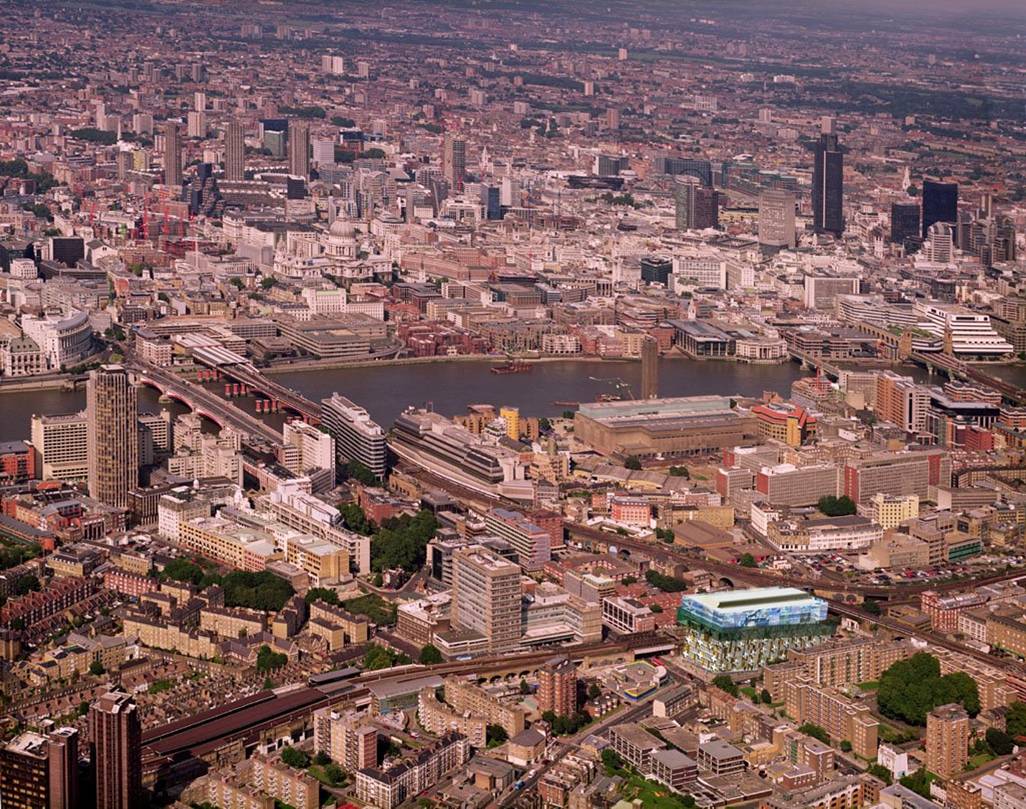
Location and Site: 86 Scoresby Street, London, England
Building Occupant Name: Southpoint General Partner Ltd.
(rentals to various tenants)
Occupancy or Function Type:
-- Primary Occupancy: Office Building
-- Mixed Occupancy: Retail (Ground Floor)
Size (Total sq m):37,098 m^2
Number of Stories Above Grade: 12
Primary Project Team:
Owner: Blackfriars Investments and Royal London Asset Management
-- Website: www.blackfriars-uk.com, www.rlam.co.uk
Architect: Alsop Architects (Will Alsop)
-- Website: www.alsoparchitects.com
MEP Engineers: Buro Happold Ltd.
-- Website: www.burohappold.com
General Contractor: Skanska UK
-- Website: www.skanska.com
Electrical Contractor: Buro Happold Ltd.
-- Website: www.burohappold.com
Structural Engineers: Buro Happold Ltd.
-- Website: www.burohappold.com
Dates of Construction: January 2004-June 2006
Architecture:
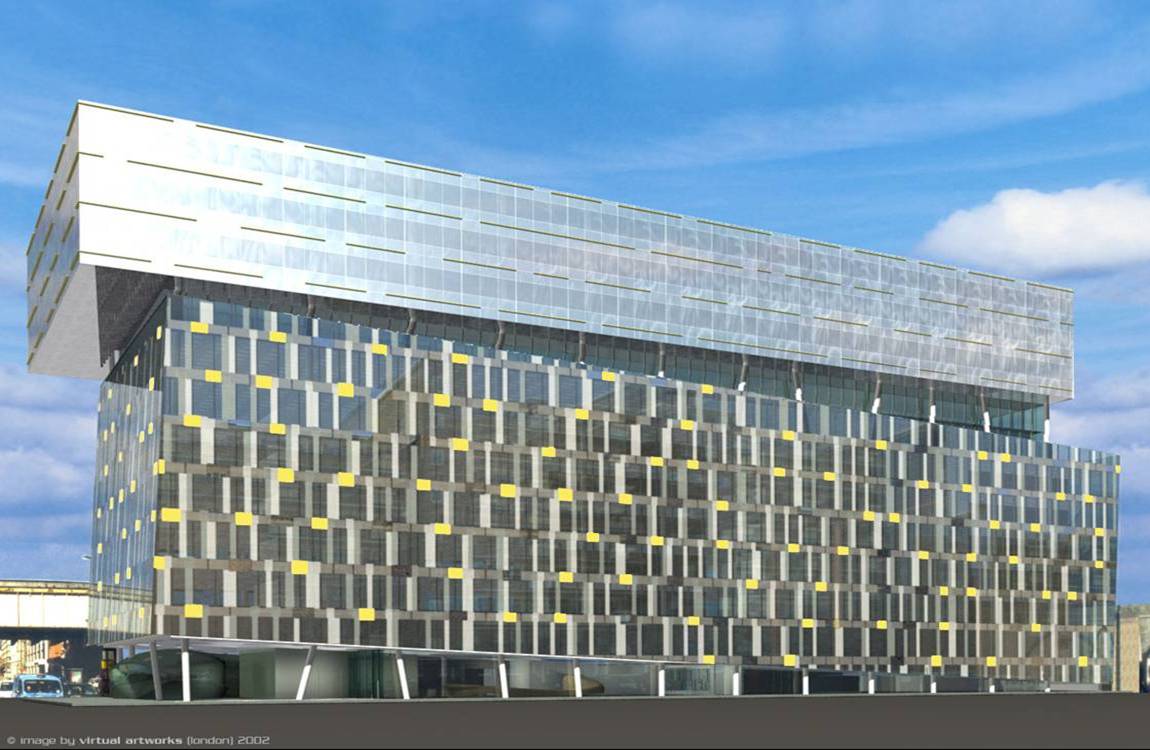
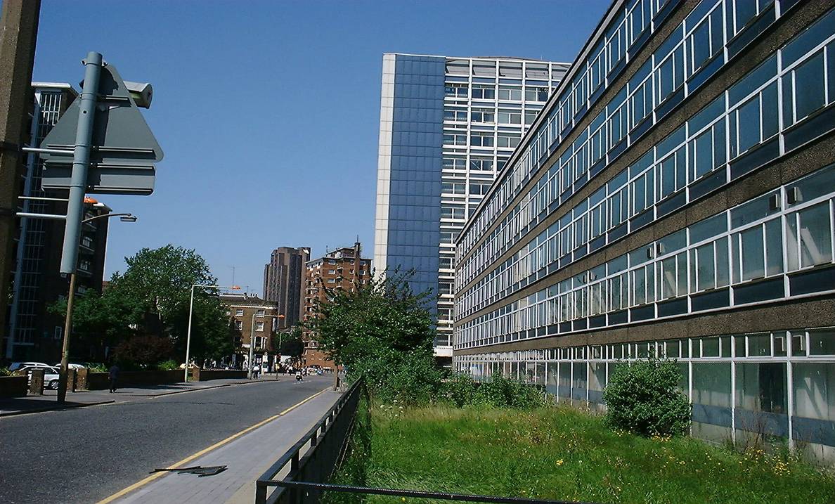
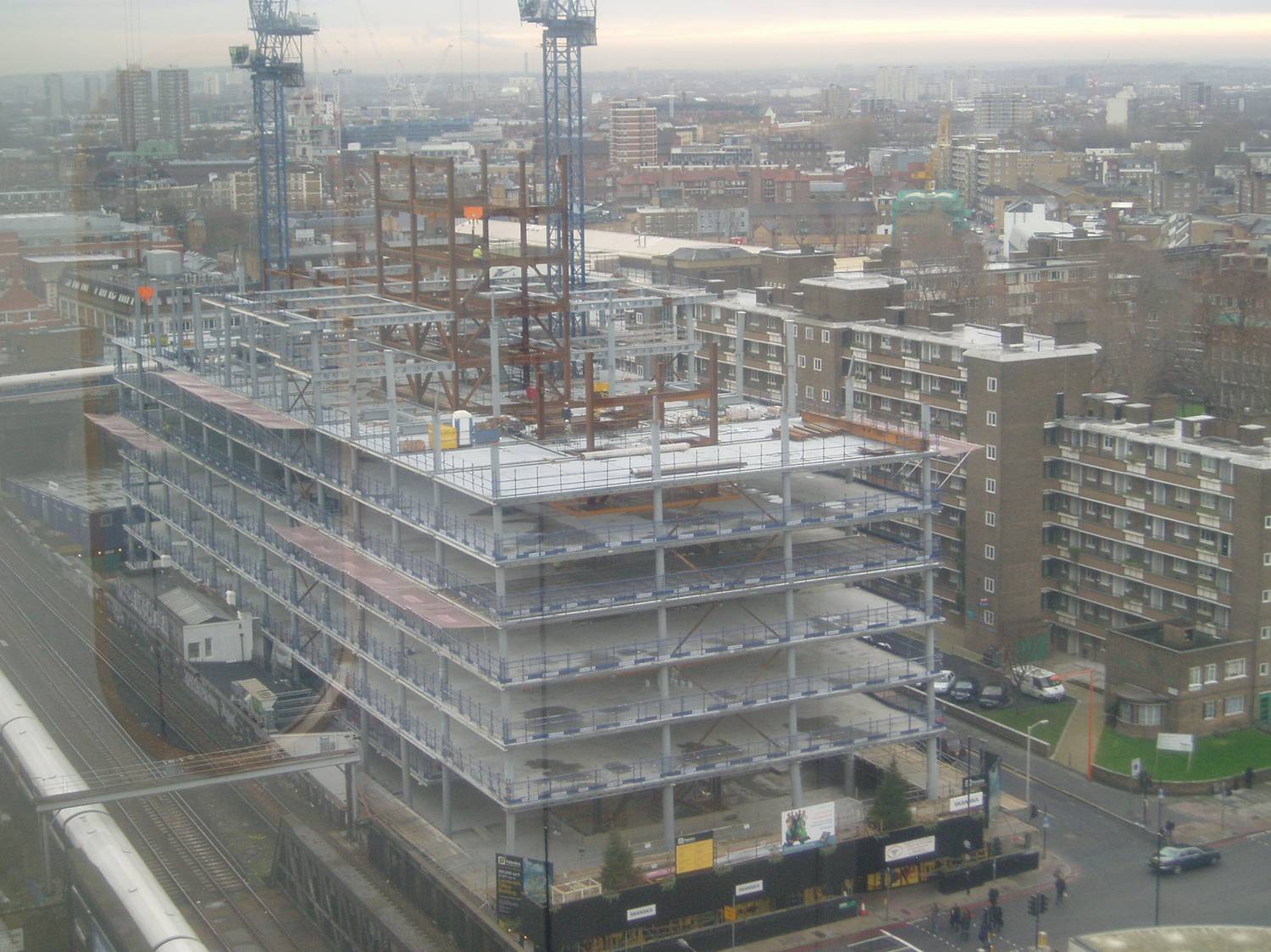
The Palestra development is currently the largest speculative office building currently under construction in London, England. Located across the street from the Southwark tube station, and just minutes from the Tate Modern museum as well as Waterloo Station, Palestra was destined to be a high-profile building. The location only enhances the ‘quirky’ design of the architect, Will Alsop from Alsop Architects.
This twelve story design is not your average office building, incorporating many dramatic features including two-story ‘dancing’ columns, large cantilevers, and tilted façade. The raked columns on the 1st and 7th stories were dubbed ‘dancing columns’ for the movement perceived by the observer due to the striking angles they are erected at. The entire design team finds humor in the community’s reaction to Palestra. One concerned neighbor even wrote a letter to the project manager voicing concerns about these columns that were severely out of plumb, not realizing the intention of the architect.
Building Envelope:
The building is fully glazed, with acoustic glazing on the North and West
sides of the bottom ‘box,’ utilizing 5 different types of double
glazing. There is an additional colored ceramic frit pattern across the
façade incorporating three colors. These ceramic frits are 60% solid
and 500mm wide.
Construction:
Build-ability was a large concern from the beginning of the design process
for Palestra because of the site’s close proximity to roads, the main
railway line from Charing Cross, and the Jubilee line on the underground.
Any crane over 8.5 ton is deemed a ‘controlled lift’ requiring
special supervision from National Rail, so every effort was made to remain
below this weight. The result was composite steel beams that were structurally
efficient as well as light-weight and east to assemble on site. The steel
frame was also strong enough to hold its own dead loads, so that the slabs
could be poured at a later date.
Because there was a
substation located in the basement of the existing building, a temporary
substation also needed to be erected on the Gambia street side to service
the site and several surrounding buildings during the construction process
and to decommission and remove the old substation as well.
Zoning and Historical:
Formerly an establishment called Orbit House located on the site. Being in such close proximity to the tube lines and above grade rails it is important to abide by weight and depth restrictions during the construction process.
Major National
Codes:
• Southpoint Development Specification – Insignia Richards Ellis
March 2002.
• BCO Guide 2000 Best Practice in Specification for Offices
• CIBSE Guide A Design Data
• CIBSE Guide B Installation and Equipment Data
• CIBSE Guide C Reference Data
• CIBSE Guide D Vertical Transportation
• CIBSE Guide G Public Health Engineering
• Institute of Plumbing Guide: Plumbing Engineering Services Design
Guide
• The IEE Regulations for Electrical Installations, BS 7671
• Electricity at Work Regulations
• The Clean Air Act
• The Control of Pollution Act
• Construction Design and Management Regulations 1994
• Health and Safety at Work Act
• Fire Precautions Act
• The Electricity (Factories Act) Special Regulations
• The Health and Safety (Display Screen Equipment) Regulations
• The Control of Substances Hazardous to Health Regulations
• Building Regulations
• British Standards for All Building Services Applications
• Fire Precautions Act
• Lift Regulations, 1999
Electrial:
A 4MVA substation will be installed in the basement plant room to service
our building and surrounding buildings formerly dependent on the substation
in Orbit House. The load will be fed by 4 transformers of 1,000kVA, 1600
amp, capacity each. 2 No. 1600 amp, 1000kVA low voltage supplies from this
substation would feed landlord plant on the roof. 4 No. 800 amp, 500kVA
low voltage supplies service tenant load via busbar risers.
Tenant supplies are
based on following electric loadings:
Lighting 15W/m^2
Small Power 30W/m^2
FCU 15W/m^2
Sub-Total 60W/m^2
Office Area 26,000 m^2
Total 1560kW 1835kVA 2780amp
Lighting:
Lighting to the open plan office spaces will be provided using recessed
modular fluorescent luminaries, fitted with high frequency control gear
and providing brightness management complying with the requirements of LG3
category 2. The lighting will be arranged on a ‘checkerboard’
grid with 2.1m between fittings. All luminaries will be plugged into a lighting
relay box mounted in the ceiling. This will allow for local switching to
be installed as partitions are moved around by the tenant, as well as space
for additional luminaries to be installed. These ‘cores’ will
also allow for future linking of automatic time-based switching and daylight
control.
 Mechanical:
The Palestra building is equipped with a gas-fired central boiler and chiller
plant. And due to the close proximity to surrounding structures as well
as the public transport, high quality fresh air is limited requiring a mechanically
ventilated design.
The boiler room is located in the basement, and runs on four boilers, three of which run at 100% to met the daily demands while the fourth is a backup during times of maintenance or it can be used as a ‘booster boiler’ to generate the morning warm-up. These boilers service a low temperature hot water system fed to AHU ventilation systems, fan coil units, and heater batteries.
The chiller plant is located on the roof and consists of seven packaged air-cooled chiller units, six of which run at full load daily, while the seventh serves as a backup unit. These units run the building’s chilled water system fed to the fan coil units and cooling coils in the air handling plant. The primary and secondary constant temperature pumps and circuits are located on the room next to the chiller units. On the office levels the owner required the design team to achieved a versatile open floor plan layout. Therefore one FCU was placed in each structural bay. Depending on the desired office layout of the tenant more FCUs can be added for increase climate control for the employees. This is based on a four-pipe fan coil system used on each office level, including water-side controls for responsible operation, room temperature sensors, and variable speed heating and chilled water pumps to conserve energy.
Because the reception area could be operating 24 hours, it was found to be more efficient to have an independent system to run separately at off-peak hours. This area is mechanically heated, cooled and ventilated in the same manner as the rest of the building. However instead of the standard FCU a Direct Expansion FCU was chosen, utilizing heat pumps rather than LTHW or chilled water.
To meet the minimum fresh air requirements two roof-mounted fresh air ventilation plants were installed.
All mechanical components
are routed through the building’s BMS (Building Management System)
to maximize efficiency.
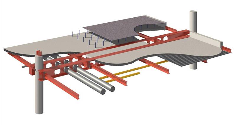
 Structural:
The structural systems of Palestra are probably one of its main selling
points. As previously mentioned there are two stories of double height ‘dancing
columns’ (raked) on the Ground-First floors as well as the 7th -8th
floors. Each column is paired so that when one is leaning one way, there
is another column leaning the exact opposite. However, the pairings are
spread out so that this isn’t quickly apparent to an observer. While
these loads balance one another, they also create a strong twisting moment
in the floor slabs that is directed to the stair and lift cores which use
the conventional steel K-braced frames.
There a larger 9m cantilever on the west side of the building as well. Because the architect placed firm restrictions on the use of diagonal bracing and more traditional support methods the result is a fully fixed Vierendeel girder from the 9th to 12th floors and tied to the primary cores. This member is made up of very substantial plate girders with flanges made from 70-80mm plates. There is as much steel on the ninth floor as the third through sixth floors combined.
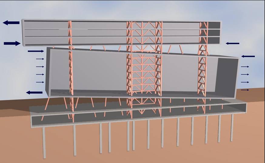
Everything between the first and seventh floor is vertical. Then there are two stories of ‘dancing columns,’ and at the ninth floor the steel grid changes from 10m x 7.5m to 12m x 7.5m because of the 1.5m cantilever all around. Due to this transition none of the columns from the 8th floor meet those on the 9th and the entire grid is offset to the west by 7.5m.
Fire Protection:
Provision has been made for mechanical smoke extract to exit through the
current ventilation extract system, extracting up to 6 air changes per hour.
In basement areas the 10 air changes per hour will be provided. The loading
bay will be naturally ventilated with 2.5% of the floor area open to fresh
air.
The upper floors will have sprinkler systems installed, following BS 5306 Part 2 regulations. Basement and ground floors’ sprinklers will be serviced by the town mains, while the upper floors will be serviced by a water storage tank in the basement. The system is distributed to the east and west cores and rise throughout the building.
Two fire fighting shafts shall be provided with smoke control within each shaft using the alternative ‘chimney’ design of smoke shaft following BRE standards. Each shaft will also be fitted with a dry riser with an outlet at each fire fighting lobby and inlets located at ground level.
Plumbing:
There are 2 No 150mm fire supplies from alternate water supplies in Blackfriars
Rpad and Union Street. There are also three water supplies entering the
site, one on Blackfriars Road, one in Union Street, and one in Gambia Street.
The Blackfriars supply will service the building’s domestic water
demands because the supply on Gambia is only 100mm diameter and the 175mm
main in Union is already servicing the fire main.
Telecommunications:
Communication risers will be provided at four locations around the building
with two risers servicing each tenant. Using galvanized cable trays the
risers can handle copper, fibre optic or blown fibre cables as required
by the tenant.
Landlord installation will include a structured data cabling scheme servicing the plant rooms, lift motor rooms, reception, and one outlet per tenant area (4 outlets per floor). A landlord telephone exchange will be installed to provide for future additions to a building telephone exchange connection. The BMS and Access Control terminals will also be connected through the structured data cabling system.
Transportation:
The central passenger transportation will consist of seven lifts located
in the central core. Each lift will be sized at 1600kg/21 persons each,
operate at 1.6 m/s, and meet disabled access requirements, achieving a waiting
time of 30 seconds as recommended by BCO. Each lift will service all twelve
floors, with one serving the basement additionally. The basement access
will be monitored through a card swipe controlled by the BMS. The lift motors
will be located in the roof plant area.
Two 630kg/8person fire fighting lifts have been provided, one in the east core and one in the west core following BS 5266 and BS 5588. They will have electric traction lift drives and operate at 1 m/s and will service ground floor through the 11th floor.
An additional goods
lift is located in the east core of the building. The good lift is 3000kg/40
persons and will also have the electric traction lift drives and service
-1 through 11. The motor room will be located in the roof plant area, with
an additional hoisting system on the 11th floor to lift materials onto the
roof.