| Home |
| Jason A. Witterman |
| Building Statistics |
| Thesis Abstract |
| Technical Assignments |
| Thesis Research |
| Thesis Proposal |
| Presentation |
| Final Report |
| Reflection |
| Senior Thesis e-Studio |
| Note: While great efforts have been taken to provide accurate and complete information on the pages of CPEP, please be aware that the information contained herewith is considered a work‐in‐progress for this thesis project. Modifications and changes related to the original building designs and construction methodologies for this senior thesis project are solely the interpretation of Jason Witterman. Changes and discrepancies in no way imply that the original design contained errors or was flawed. Differing assumptions, code references, requirements, and methodologies have been incorporated into this thesis project; therefore, investigation results may vary from the original design. |
|
Building Statistics
|
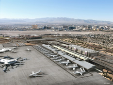
| McCarran International Airport –Terminal 3 |
| |
|
5757 Wayne Newton Boulevard
Las Vegas Nevada 89119 |
| |
| The new terminal is located on the north east portion of the airport site. This area is to the north of Satellite D, and east of Terminal 1. |
| |
|
| Clark County Department of Aviation |
| |
|
| The building has non-separated mixed occupancy, including: |
|
A-2
A-3
B
M
F-1
S-1 |
Lounges, and Dining Areas
Passenger Check-In, Waiting Areas, Ticketing, Baggage Claim, Conference Rooms, Break Rooms, ATS Stations
Offices
Retail
Mechanical / Electrical Rooms
Storage |
|
Approximately 1.8 Million SF |
| |
|
| Terminal 3 will consist of 5 total stories. The basement level will be entirely below grade, and the uppermost level is dedicated to mechanical penthouse space. |
| |
|
Construction Manager
Bechtel Corporation
Las Vegas, NV
www.bechtel.com |
Architect / Civil Engineer
PGAL, LLC
Las Vegas, NV
www.pgal.com |
Architecture
Welles Pugsley Architects, LLP
Las Vegas, NV
www.wellespugsleyarchitect.com |
Interior Architecture
Robert A. Fielden
Las Vegas, NV |
Baggage Systems
BNP Associates
Danbury, CT
www.bnpassociates.com |
Structural Engineer
Walter P. Moore
Las Vegas, NV
www.walterpmoore.com |
MEP Engineer
JBA Consulting Engineers
Las Vegas, NV
jbace.com |
Cost Estimator
Faithful + Gould
Houston, TX
www.fgould.com |
Fire Protection Engineer
Rolf Jensen & Associates
Las Vegas, NV
www.rjagroup.com |
Information Technology
ARUP
San Francisco, CA
www.arup.com |
| |
|
Security Consultant
Glover & Associates
Roseville, CA
www.gloverinc.com |
Automated Transportation System
Jakes Associates
Henderson, NV |
Transportation Consultant
Lerch Bates & Associates
San Juan Capistrano, CA
www.lerchbates.com |
Surveyor
Barajas & Associates
Las Vegas, NV
www.bai.com |
Landscape Consultant
Hill Clark & Associates
Las Vegas, NV |
Geotechnical
Kleinfelder Inc.
Las Vegas, NV
www.kleinfelder.com |
Civil Engineer
Louis Berger
Las Vegas, NV
louisberger.com |
Food Service
Dieli Howe Smith
San Diego, CA
www.rwsmithco.com |
Concessions Consultant
Center for Airport Management
Libertyville, IL
www.centerair.com |
Acoustics & Paging
Coffeen Fricke & Associates
Lenexa, KS
www.cfaconsulting.com |
Lighting Design
Horton Lees Brogden
Culver City, CA
www.hlblighting.com |
Signage
Selbert Perkins Design
Playa Del Rey, CA
www.selbertperkins.com |
| |
|
| Work on the early package portion of the project began in April of 2007. Construction for the new Central Utility Plant is expected to begin in early 2008, and finish in mid 2009. The terminal itself is expected to be given notice to proceed in mid 2008, with a completion date of early 2011. |
| |
|
The owner has requested that this information not be posted. |
| |
| Terminal 3 will be a “unit” terminal at McCarran International Airport, as it will not be dependent on the existing terminals. The new terminal will provide 14 new gates, a significant addition to the already existing 95 gates. These new gates will serve both domestic and international flights, so Terminal 3 will also include customs and border patrol services. While the new terminal follows a space planning similar to that of the existing terminals, it will incorporate more modern design elements. |
| |
| Terminal 3 consists of 5 levels. The below grade basement level includes mechanical and electrical rooms, storage, and Automated Transportation System (ATS) maintenance areas. Level 0 is below grade on the airside of the terminal, and at grade on the landside. It includes baggage claim, customs, an ATS station serving Satellite D, and back-of-house support facilities. This level also contains TSA passenger screening as Satellite D is a fully secure building. Level 1 is at grade on the airside of the terminal and above grade on the landside. It houses the baggage screening systems, airline support area, and other back-of-house facilities. This level is fully secure with the exception of a landing connecting Level 0 and Level 2. This landing will provide access from a new parking garage to be built with Terminal 3. Level 2 contains the new gates, concessions, gaming areas, concourses, ticketing counters, offices, and additional back-of-house facilities. Level 3 of the terminal will consist only of mechanical penthouse spaces. |
| |
| Special attention is drawn to the requirement for full separation of secure and non-secure areas of the new terminal. In addition, the international gates require sterile circulation to prevent access to non-sterile areas without passengers having first cleared customs. These requirements have a significant impact on circulation and building egress as they must be maintained even in the event of an emergency. |
|
|
IBC 2000
UFC 2000, UPC 2000, UMC 2000
NEC 2005
NFPA, Nevada State Fire Marshal Requirements
Southern Nevada Amendments to any of the above |
| |
|
Clark County zoning laws indicate the property is zoned as P-F (Public Facility). |
| |
|
No historical requirements apply to this building. |
| |
|
Although a small portion of the north elevation is clad with stone paneling, a majority of the walls at Terminal 3 are clad in zinc paneling. Other exceptions to this paneling exist on the lower portions of the building. For example, cast in place concrete is used for the lower level walls at grade on Level 0 of the north elevation, and also at Levels 0 and 1 of the east and west elevations. Similarly, the lower level of the south elevation contains CMU block at level 1 which is at grade on the landside portion of the terminal. |
| |
The zinc panel wall system is installed over a layer of ⅝” gypsum sheathing board, with a weather barrier installed between the two layers. This cladding system is installed over 6” metal studs with R-19 batt insulation in the wall cavity. The interior of the wall is typically covered with either painted gypsum board sheathing or porcelain wall tile. A large portion of the walls in the terminal also include tinted glazing. Most of this glazing is achieved with an aluminum curtain wall system, and 1¼” nominal thickness insulated glazing units. |
| |
The south side roofing of Terminal 3 is constructed of a zinc paneling system similar to the walls. These zinc roof panels are installed over a ¾” vent sheet, membrane underlayment, and ½” gypsum sheathing board. Below this sheathing are two layers of 2½” rigid insulation, ⅝” gypsum sheathing board, and 1½” metal roof deck. The north side roofing consists of a singly ply membrane roof over ¼” glass material recovery board. Below this are two layers of 1½” rigid insulation, ⅝” gypsum sheathing board, and a 1½” metal roof deck. |
| |
Terminal 3 is served by (88) air handling units. The concourses and baggage handling / screening areas are served by (27) of these air handling units. These (27) units are classified as Single Zone Variable Air Volume (SZ VAV) systems in that they are provided with variable speed drives. Another (37) VAV air handling units serve baggage claim, airline operations, TSA screening, and ticketing. These air handling units also serve other minor private and public spaces throughout the terminal. Similar to the SZ VAV systems, these units also contain variable speed drives. The remaining (24) air handling units are Constant Volume (CV) systems serving electrical substations throughout the building.
The SV VAV and VAV systems are all provided with demand controlled ventilation. Those systems serving the baggage handling areas are provided with carbon monoxide sensors due to the operation of combustion engine driven baggage tugs. Those areas served by the VAV systems are provided with carbon dioxide sensors.
A new central plant is being constructed to serve Terminal 3. This central plant will include (5) 2,200 ton centrifugal chillers and (6) 21,000 MBH boilers. An additional chiller and boiler of equal capacity will be provided as standby. An additional (3) air handling units are provided to condition the central plant. This central plant has also been sized to have enough capacity to serve Satellite D. This allows for Satellite D to be served by the existing central plant or the new central plant. |
| |
A new Nevada Power yard will be provided at the new central plant. This power yard will provide (4) 15kV service entrance switchgear sections. Terminal 3 has also been designed to receive service from (2) separate substations. This is done to reduce downtime in the event of an outage. Power distribution to the terminal will be provided by (4) 10 MVA main feeders and (4) 10 MVA dedicated back up feeders. Due to the nature of the facility, it is also necessary to provide emergency power for critical building systems. This emergency service is provided by (4) 2,000 kW/2500 kVA, 480 / 277 V diesel generators. These generators are provided with step up transformers and automatic paralleling switchgear. |
| |
The foundation for Terminal 3 is made from 3’-6’ diameter drilled piers ranging from 35’-75’ in depth. The length of the terminal required that the building be divided into six separate structures through the use of (5) isolation joints. The terminal is a steel framed building with a typical grid spacing of 40’. There are a few exceptions to this with some bays spaced at 28’ or 48’. Typical girders running in the East-West direction will be W33’s. Typical beam sizes range from W24’s for 40 ft bays, W27’s for 48 ft bays, and W18’s for 28 ft bays. The floors of the terminal will be comprised of 4.5” thick concrete slab over 3” composite metal deck. Lateral loads in the building will be resisted through the use of braced frames. The structure is also fire-rated. |
| |
A new fire alarm and detection system, as well as an automatic sprinkler system will be provided throughout the new terminal. In addition, standpipes will be provided as required by NFPA 415. Two (2) new fire pumps will be provided to serve the new terminal.
The ATS station at the north end of the tunnel will be served by this new system, while the ATS station at the south end of the tunnel will be served by an expansion of the existing Satellite D fire protection systems, including fire pumps. Additionally, the owner requests a deluge system be provided at the station platforms. This deluge system will be installed at track level to protect the loading and unloading platforms from a fire beneath the train. A similar system is in place at the existing Satellite D station and both systems are to be operated manually from the main control room.
Terminal 3 is also provided with a fire annunciation system for evacuation and emergency communications. All fire alarm systems will be tied into the overall fire alarm system located in the main control room on the 4th floor of the existing main terminal (Terminal 1). |
| |
In July of 2007, the site was cleared for Terminal 3. This was a civil engineering project that required the realignment of Russel Road as the old road was located where Terminal 3 will be constructed.
As mentioned above, actual work on Terminal 3 began in April 2007 with the issue of early package work. This package includes the foundations for Terminal 3, below grade piping, and work on the service corridor. This package also included some modifications to the existing ATS shell tunnel.
While the dates for the remaining work have yet to be finalized, the following dates are the most current projections. Terminal 3 itself is scheduled to be bid in the fourth quarter of 2007. It is expected that notice to proceed will be given in mid 2008. The expected completion date for the terminal is early 2011. The new central plant is scheduled to be bid under a separate contract in January 2008. Construction on the central plant will likely begin in early to mid 2008 and finish in mid to late 2009.
A new parking garage will be constructed concurrently with Terminal 3. This parking garage will connect to Terminal 3 via pedestrian bridges at level 1 of the terminal. This work is being designed by a different design team, and will also be issued under a separate contract. |
| |
An ATS station will be included in the design of the new terminal, and will be connected to an existing station at Satellite D by an 800 ft guide way and pedestrian tunnel.
The terminal contains (18) public elevators and (15) back of house elevators. Two (2) of these elevators are designated as emergency elevators. The terminal is also provided with numerous moving sidewalks and escalators throughout. |
| |
Since Terminal 3 is a stand alone terminal, it requires an independent baggage handling and screening system. This series of conveyor belts serves outbound baggage check on level 2, inbound / outbound baggage screening and handling on level 1, and inbound baggage claim on level 1. |
| |
Terminal 3 includes all necessary telecommunication wiring for the various system that will be used throughout. These will include items such as computers at the ticketing counters and the boarding gates. Similarly, various information displays will be utilized throughout the building to notify passengers of the latest travel information. Additionally, a paging system is being installed throughout the building. This system will allow for common general announcements, as well as urgent personal notifications. |
| |
|