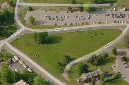
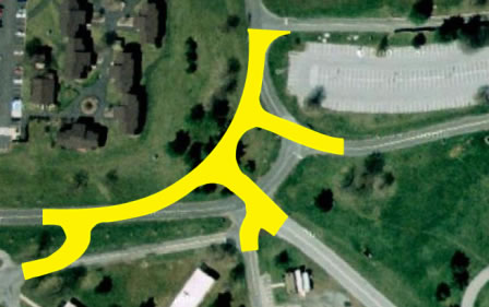
The road re-alignment created several major logistical issues for the construction team. Lion Life drive is a major access point to the hospital from the east. The medical center receives its medical supplies for the next day’s surgeries/patients the night before so closing any part of the road was not an option. To solve this problem the construction team broke the road re-alignment into several phases and constructed temporary roads to keep traffic flowing during the entire 9 week duration.
PRIMARY ENGINEERING SYSTEMS
STRUCTURAL
PSUHMC’s Support Services Building has a rigid structural steel superstructure with micropiles, pilecaps, and grade beams serving as the deep and shallow foundations. Located at the exterior stair towers and elevators are load bearing masonry walls that help act as shear walls. Due to the primary function of the building and interior layout, all bay sizes are different. Typical column sizes are W10x33 except for the 11 columns surrounding the 3,000 SF, 2-story Central Campus Storage in the center of the building. Typical beam and girder sizes are W21x44, W14x22, and W18x35. Supporting both the lower roof and upper roof is a combination of K-Series steel joists.
Due to the karst rock formations in the area, the Geotechnical Engineer in his geotechnical report suggested the micropile foundation system. There are a total of 152 7”, 120-ton micropiles with an average length of 67’ with a minimum embedment of 12’ into bedrock. Of those 152, 60 are to be battered piles to help support lateral loads.
There are two types of floor construction in the Support Services Building; composite slab on metal deck and slab on grad with two different types of slabs. The floor slab at the lowest level (tunnel level) is a 12” one-way slab on grade beams with #8 reinforcing 12” O.C. in the N-S direction and #5 bar 12” O.C. in the E-W direction. The second slab on grade is the floor for the first level. It is a 6” slab with #4 reinforcing bars located 16” O.C. in both directions. The elevated floor slabs are 3 ½” normal weight concrete on composite metal deck with W6x6 W2.9xW2.9 welded wire fabric and ¾” shear studs.
MECHANICAL
The primary mechanical system for the Support Services Building is a VAV system with reheat coils located at each VAV. In total the system contains 44 VAV’s capable of providing between 150 – 1,340 CFM. At the heart of the VAV system is the three roof top units (RTU’s) and two condensing boilers. Total the three RTU’s have a 136 Ton cooling capacity, 1,214 MBH heating capacity and are capable of providing 30,000 CFM’s to the building. Located in the mechanical room on the second floor, each boiler is capable of providing 45 GPM at 140° supply water temperature which is equivalent to 705 MBH.
To help maintain a high indoor air quality the Support Services Building is also equipped with a total of 18 exhaust fans ranging in size from 100 – 2000 CFM to keep harmful contaminants from re-entering the air system. The Support Services Building also has two rooftop make-up air units (MAU) that service the Paint Shop and Open Dock Area. To help achieve the LEED Certified rating the boilers and (MAU’s) on the project are run off natural gas and all filers have a MERV-8 rating.
Located in the stair towers and vestibules are Cabinet Unit Heaters (CUH) to help heat these spaces. There are for different CUH’s on the project ranging in size from 670 – 1210 CFM. To cool the IT rooms, and cool/heat the electrical and elevator machine rooms there is total of five ductless Air Conditioning Units (ACC) which are each individually connected to an Air Cooled Condensing/Heat Pump Unit (CNU) on the roof. All units have an energy efficiency rating of 16 SEER. The ACC’s and CNU’s for the two IT rooms are capable of providing 1 ton of cooling each. The ACC and CNU servicing the electrical room is capable of providing 1.5 tons of cooling and 20,400 BTUs of heating. Lastly the two ACC’s and CNU’s servicing the two elevator machine rooms are capable of providing 3/4 ton cooling and 12,200 BTU’s of heating.
ELECTRICAL
PSUHMC’s Support Services Building gets it power from an existing electrical ductbank that traverses the eastern side of the site. From the ductbank, the primary source (3 #300 KCMIL 15KV EPR cables) and the secondary source (3# 500 KCMIL EPR cables) feed into a PMH-9 Sectionalizing Switch with automatic source transfer control. From the sectionalizing switch 3 #2 15KV EPR cables run to an owner supplied 500KVA transformer. The primary side of the transformer takes the 13.8 KV incoming feed and is stepped down to 277/480V-3Ø on the secondary side feed to building.
From the transformer 2 sets of 4#350KCMIL run to the 600A main distribution panel inside the electrical room located on the 1st floor. From the main distribution panel the power is distributed to either the 3 Roof Top Units (RTU’s), 2 elevators, one of 5 panelboards, or to a 150KVA transformer to step the power down to 208Y/120. From the 150KVA transformer the 208Y/120 is distributed to an additional 8 panelboards.
LIGHTING
There are 20 different types of lighting fixtures in the Support Services Building. Typically all lighting on the project is run off 277V except for 3 fixtures. The other 3 fixtures are 120V. Mostly the fixtures are 2 bulb (32W T8) industrial fluorescent pendent lights. All fluorescent lamps are be a minimum 4100K color temperature, 85 CRI, have an initial lumen output of 3100 lumens, and a mean lumen output of 2950 lumens. The other interior lights are a combination of recessed down lights, walk mounted, and surface mounted. All of the exterior lights are on their own separate relay panel controlled Building Management System.
ADDITIONAL ENGINEERING SUPPORT SYSTEMS
PLUMBING
PSUHMC’s Support Services Building domestic water is supplied via a 6” domestic water line reduced to 3” to feed the building. At the heart of the domestic water system is two hot water heaters located in the 2nd floor mechanical room. Each hot water heater is a natural gas fired unit with a 100 gallon capacity. Another part of the plumbing system is the High Pressure Spray System located in the Wash Bay in the southeastern corner of the building. The system is a Splash N Dash model manufactured by the Jim Coleman Company.
FIRE PROTECTION SYSTEM
There are two types of fire protection systems for the Support Services Building. The final design of both is the responsibility of the Fire Protection subcontractor. The first type of system is an Early Suppression Fast Response (ESFR) and is to be located in the Central Campus Storage located in the center of the building. The remaining parts of the building will be covered by a wet-sprinkler system with the tunnel level and1st floor being classified as Ordinary Hazard Group 2, and the 2nd floor being classified as Light Hazard Group.
COMPRESSED AIR SYSTEM
To meet the demands of the various support shops located in the building, the new Support Services Building will feature a compressed air system. The system is comprised of 1” main line with ¾” drops to the 13 different compressed air outlets. The piping is galvanized steel schedule 40. Each outlet is Ingersoll Rand Series 3000 with a 1-140 PSI regulator. At the heart of the system is a 2-stage Ingersoll Rand Model 7100E15-FPT30 Air Compressor with a 120 gallon tank capacity capable of supplying 51 CFM of compressed air.
VERTICAL TRANSPORTATION
There will be two elevators located within the new Support Services Building. Both are traction gearless type with the elevator machine rooms located on the roof. Each elevator runs off 480V, 3-phase power. The first elevator is a 3000lb passenger elevator servicing the 1st and 2nd floors. The second elevator is a 12,000lb freight elevator servicing the tunnel level as well as the 1st and 2nd floors.
LOW-VOLTAGE SYSTEMS
Included in the Support Services Building are several low-voltage systems. These include a fire-alarm system, security system, and a telecommunications system. The fire alarm system is to be purchased and installed by PSUHMC’s fire alarm contractor, Johnson Controls, and is to be an extension of the Medical Centers Notifier Alarm Fire Alarm that was installed and maintained by Johnson Controls. The security system includes card readers at all exterior doors as well the installation of new card readers inside the tunnel at the Animal Research Facility (ARF) end and at the main hospital end. Also included in the security system is 4 security cameras. Giving the use of the building, the telecommunications system is fairly basic. Typically there is a phone line and data outlets located in all of the offices as well as some of the shops.
PAINT BOOTH
Included in the Support Services Building is a fully functional, self-standing paint booth. The paint booth is located inside the paint shop which has its own make-up air system. The paint booth itself is a Paint Booth Technologies Model PBT-IE-1212. The dimensions of the booth are 12’ x 12’ x 12’h. Also the paint booth is connected to its own exhaust system which is a 30” diameter round ductwork made from stainless steel. |