ORCHARD PLAZA
SOUTHWEST PENNSYLVANIA
CHRISTOPHER DUARTE
STRUCTURAL
ORCHARD PLAZA SOUTHWEST PENNSYLVANIA CHRISTOPHER DUARTE STRUCTURAL
|
|
|---|
| HOME | STUDENT BIOGRAPHY | BUILDING STATISTICS | THESIS ABSTRACT | TECHNICAL ASSIGNMENTS | THESIS PROPOSAL | PRESENTATION | FINAL REPORT | REFLECTION | eStudio |
|---|
| BUILDING STATISTICS - PART 1 |
|---|
| GENERAL BUILDING DATA | Building Name...................... Orchard Plaza Location................................ Southwest Pennsylvania Occupancy............................. Office & Retail Size......................................... 144,000 square feet Number of Stories................. 6 Date of Completion............... December 2006 Cost........................................ $18.5 million Project Delivery Method...... Design-Bid-Build |
|
|---|---|---|
| PROJECT TEAM | Owner..................................... Millcraft Investments Architect................................. STRADA Structural Engineer................ Barber & Hoffman, Inc. Civil Engineer......................... GAI Consulrtants, Inc. MEP Engineers...................... Allen & Shariff Corporation |
|
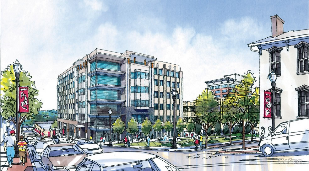
| ARCHITECTURE | Orchard Plaza contains street level retail on the ground and first floors with office space on the remaining second through sixth floors. The base facades are primarily limestone that transition to brick masonry at the base of the second level. |
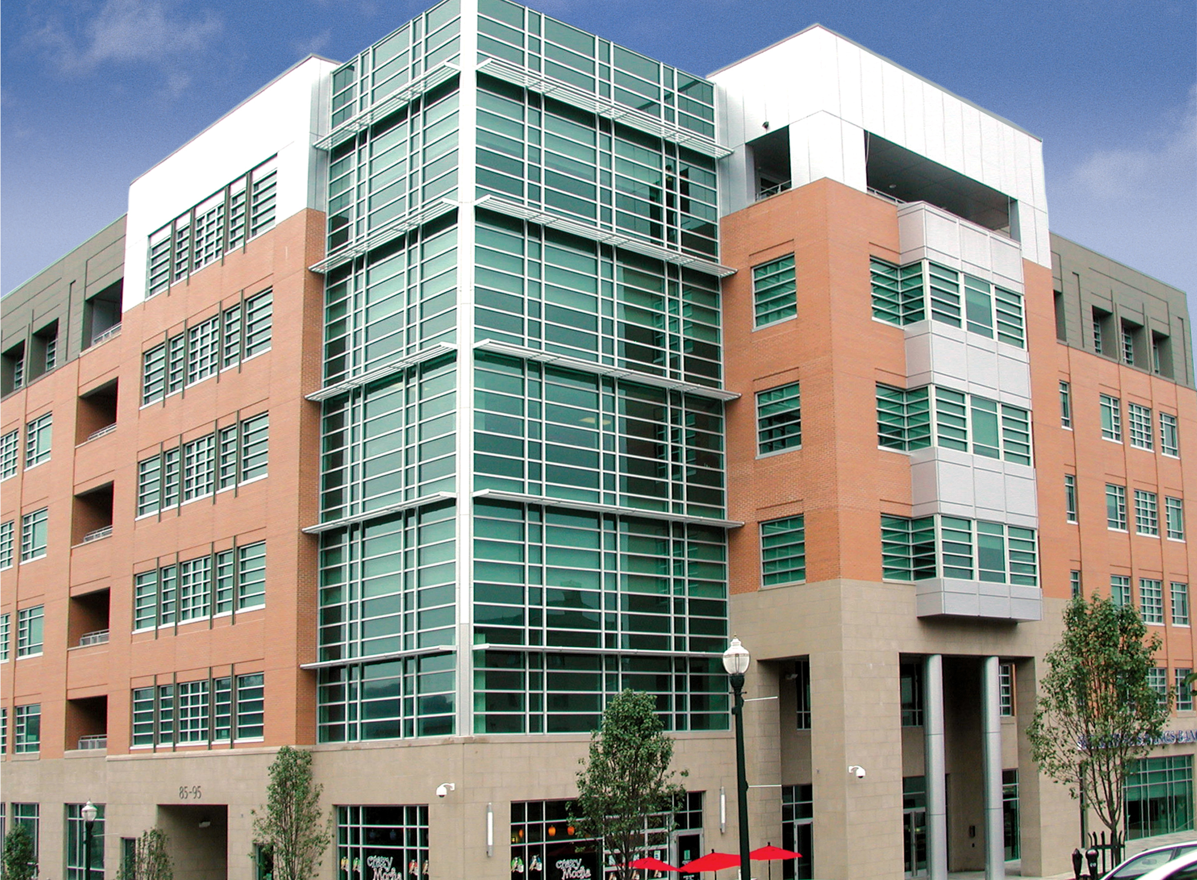 |
| BUILDING ENCLOSURE | FACADE The ground floor includes a limestone base that supports a masonry front that begins on the first floor and extends to the fifth floor. The top floor is wraped in metal paneling to add a contemprary cap to the structure. The southwest corner of the building also includes a full height curtain wall. ROOFING The roof of Orchard Plaza is generic and features walk ways for servicing of the rooftop HVAC units. Each of the three rooftop units rest on a concrete pad and dampners. |
|
| SUSTAINABILITY FEATURES | This building has no Sustainability features. |
|
| STRUCTURE | FOUNDATION Caissons ranging from thirty to seventy-six inches in diameter secure the columns to the soil. The caisson notes specify that the caisson depth must extend a minimum of one foot into limestone bedrock. Longitudinal rebar extends a minimum of ten feet below the top of each caisson. Caisson caps serve as column base plate bolt anchors. Their height varies per column. Grade beams of widths varying from eighteen to thirty-two inches and depths up to three feet provide a grid of foundation between most columns. Slabs on grade with expansion joints between grade beams and slabs on grade and between adjacent slabs compose the first floor (ground floor) of the building. Slabs on grade are reinforced with welded wire fabric placed between one and one and one-half inches below the top of the slab. Special reinforcing rebar is added around slab openings. Rebar extends multiple feet beyond the slab opening edge and is accompanied by a diagonal bar at opening corners. Due to the grade change over the building’s site, there is a one story change in elevation over the site beginning on the western side at the first floor and raising up to the second floor on the eastern side. In order to accommodate this change while maintaining the entire first floor for usable space, a cast-in-place concrete wall is used on the north, east, and south exterior walls. SUPERSTRUCTURE Typical floor framing consists of beams and girder construction of varying sizes. Figure 7 shows a typical beam and girder layout for the first floor. Floors two through six follow a very similar design. Beams range in size from W16x31 to W21x44 while girders vary from W24x68 to W 30x99 with exceptions for both beams and girders surrounding floor openings. Floors two through five utilize a composite decking system comprised of normal weight concrete, two inch 18 gauge composite decking, and welded wire framing placed one inch from the top of the slab. Where exterior brick veneer requires support, deeper beams run the length of the exterior with 3/8” plate welded perpendicular to of the beam. A system of HSS tubing, shims, and angle form the brick veneer support while an angle brace runs up to the beam behind or is joined directly with a double angle connection. Similar connections are done for masonry veneer facades on the lower floors. Some exterior edges also include small cantilevers. All columns rest on caissons or grade beams as described earlier. Column base plates are typically mounted to caissons with four anchor bolts as shown in gray in Figure 10. Additional base plates and anchor bolts are added are added for any base joints with the lateral system. Column splices occur four feet above the floor slab of the first, third, and fifth floor unless required to be at a different height to avoid brace connections. Base columns range from W14x99 on the exterior to W14x257 on the interior. LATERAL SYSTEM The primary lateral load resisting elements are moment frames formed from W-shape beams and HSS tubing. The orientation of these frames is distributed evenly between the north-south and east-west direction to adequately accommodate lateral loading from any direction. Lateral frame connections are characterized by welded plates at both ends of the HSS tube, shown in purple, and are welded to columns and girders as seen in Figure 14 below. This connection requires a significant amount of prefabricated welding and field welding. Stiffener plates must also be added on both sides girder webs at the upper connection of the HSS tube and respective connection plate. The lateral moment frames constitute the majority of wind resistance framing in the building. The expected direction of forces on the base plates are shown with orange arrows. The frames are distributed, though not proven yet with calculations, appropriately so that most floor bays share at least one edge with one of the moment frames. This layout provides for a more stable structure as there are no large areas without lateral resistance. Symmetry in the frames allows them to act equally effective regardless of wind direction. |
|
| MECHANICAL | The building is served by two rooftop variable air volume (VAV) units while a boiler and reheat system provide the heat needed when necessary. Orchard Plaza is equipped with an air conditioning unit capable of 26,000 btu/hr of cooling capacity. |
|
| ELECTRICAL | A variety of thirteen different lighting fixutures illuminate the interior and workspaces of the building. The building is served by a 480/277V power line that enters the building on the northern side into the ground floor main electrical room. |
|
| CONSTRUCTION | The construction of Orchard Plaza was completed in December of 2006. Excavation was required on the northern and eastern areas of the site in order to cast the building foundation/retaining wall. Underground parking was not required as there is a parking garage adjacent to the site. A design-bid-build process was used for the construction of the project. |
|
| FIRE PROTECTION | A grid of recessed sprinkler heads protect every floor of the building. Standpipes are located in both stairwells and serve the building's fire protection system. Additional sprinklers are located in the elevator shaft at the rooftop level. |
|
| TRANSPORTATION | Three elevators are located near the east side of the building. Each run between the ground and sixth floor. Additionally, two stairwells provide safe means of egress from the building in accordance with fire code regulatuions. |
|
| TELECOMMUNICATIONS |
Floors two through six include a data room that is specially equipped to house and protect the occupants servers and various electronic and communication needs. The data rooms are loacted adjacent to the building's core of restrooms. |
|
| SENIOR THESIS HOME | PENN STATE | PENN STATE ARCHITECTURAL ENGINEERING | AE COMPUTER LABS |
|---|