general building data |
Building name |
Engineering Center
Location and Site |
Oakland University, Rochester, Michigan
Building Occupant Name |
Oakland University, School of Engineering and Computer Science
Occupancy or function types |
2 Buildings separated by firewall; Building A is MBC TYPE IIB, NFPA TYPE II(000) and Building B is MBC TYPE
IB, NFPA TYPE II(222)
Size |
136,653 SF (Gross)
Number of stories above grade / total levels |
5 / 5
Primary project team |
Dates of construction |
Actual cost information |
Project delivery method |
|
.jpg)
Figure 1 | Southeast Perspective | Courtesy of SmithGroupJJR
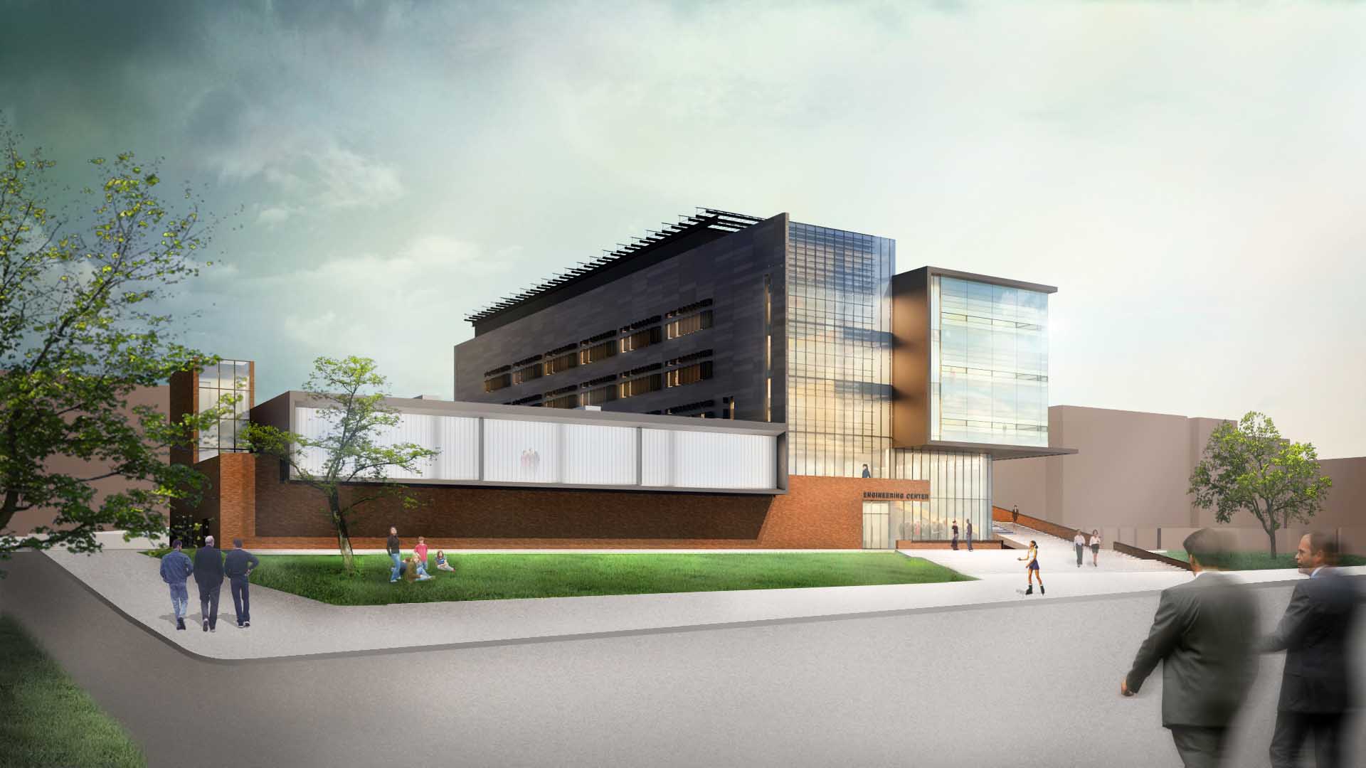
Figure 2 | Southwest Perspective | Courtesy of SmithGroupJJR
Design |
This new Engineering Center for Oakland University’s campus is a much needed addition to the campus in
terms of faculty office, classroom and research lab space for the campus’ ever growing school of
engineering and computer science. As the new heart of Oakland University’s School of Engineering and
Computer Science, this building needs to provide the appropriate spaces for the improvement of teaching,
learning and research. The building’s program of spaces includes, 1000 seats of classroom space, 200 seat
lecture hall, SECS (School of Engineering and Computer Sciences) office spaces, departmental office
spaces, faculty office spaces, student office spaces, class laboratories,research laboratories, clean rooms
and study spaces including a café. This building, for those involved at Oakland University, is a symbol of
future growth of the university and the School of Engineering and Computer Science (SECS),
interdisciplinary collaboration and an incubator of ideas in research and learning.
The design aesthetics of the building are intended to be very raw and geometric in nature, seen in Figures 1
and 2 above. That being said, there were attempts, architecturally, to tie the building into the campus fabric
through the use of the brick on the lower levels to reflect the older buildings on the campus and the modern
feeling panels and curtain walls to reflect the more recent projects completed on the campus. The building sits
on a hill and creates a nice transition from the upper level near the campus library to the lower parking area as
well as helping to create more of a quad feeling in the upper area and a nice stair feature for transition
through the campus. The new Engineering Center is to be a tangible symbol of the future for Oakland
University and the School of Engineering and Computer Science.
National Model Codes |
The main codes used by the architects and engineers while designing include: The Michigan Building Code
2009 (MBC 2009) which is an amended version of IBC 2009; the Michigan Fire Prevention Code MFPC which
adopts NFPA 1; Michigan 2008 Electrical Code incorporating National Electrical Code 2008 (NEC); the
Michigan Plumbing Code 2009 (MPC) which is an amended version of the International Plumbing Code 2009;
the Michigan Mechanical Code 2009 (MMC) which is an amended version of the International Mechanical
Code 2009; 2003 ICC/ANSI A117.1 2010 ADA Standards for accessibility and usability.
Zoning |
For zoning purposes, Oakland University is located in both the Auburn Hills zone and the Rochester Hills
zone. The Engineering Center will be situated within the Auburn Hills zoning ordinance under a special
purposes designation. According to Article X, Section 1000 Special Land Uses Permitted, colleges,
universities or other institutions of higher learning have to comply with three stipulations: First being that
to be considered in this special purpose designation the site must be greater than 40 acres. The second,
is that the ingress and egress from the site must be onto a major or secondary thoroughfare. And third,
no building can be closer than 75 feet from any property line unless it is for one family residential purposes.
Historic Requirements |
There are no historic requirements to adhere to in the design of this new engineering building for Oakland
University’s campus.
Building Facades |
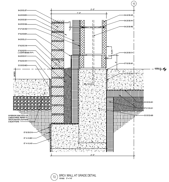
Brick Walls | The exterior brick facades, found on the lower two floors of the building, are typically made
up of a veneer face brick tied back into a CMU wall with dovetail wire anchors, an air space, fluid-applied
vapor-retarding membrane, then the concrete wall followed by the interior wall finishes. The typical
construction is shown below in Figure 3.
Figure 3 | Brick Wall Section | Courtesy of SmithGroupJJR
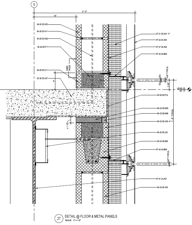
Panel Walls | The metal panel walls, found in the upper floors of the Engineering Center, include a zinc
faced composite wall panel connected to the structure with adjustable framing angles which allows for
room for an air space and XPS-1 extruded-polyestrene board insulation followed by the concrete masonry
unit wall assembly.
Figure 4 | Panel Wall Section | Courtesy of SmithGroupJJR
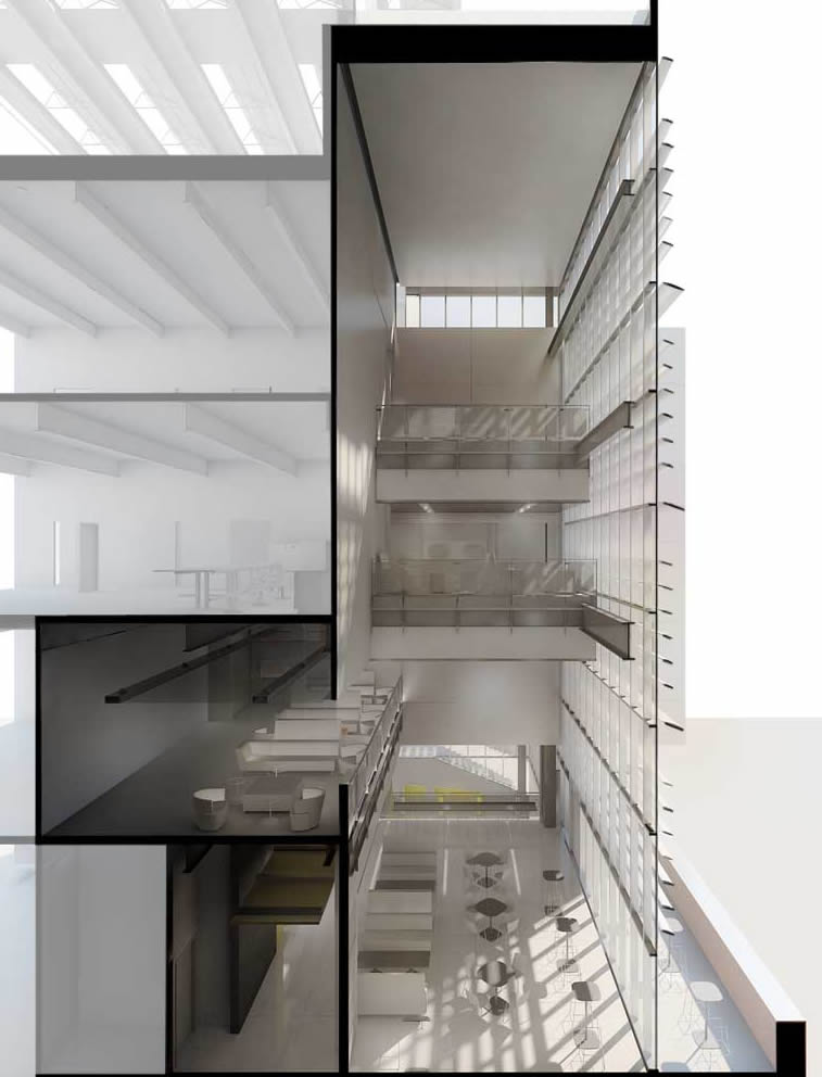
Curtain Walls | The curtain wall system utilizes two sided structural sealant glazed curtain wall with 1”
insulating glass with ½” argon airspace and a visible transmittance of 79% as well as vertical mullion
mounted sunshade system which is horizontal louver based and angled down at 20 degrees.
Figure 5 | Atrium and Cafe Section Showing Curtain Wall | Courtesy of SmithGroupJJR
Roofing |
A typical roof section, shown in Figure 6, contains, from the structure to the exterior, surface
conditioner, fluid-applied protected membrane roofing, protection course, drainage panel, three inches of
semi-rigid insulation, a filter fabric and another later of concrete which is a precast concrete roof paver.
For the garden roof assembly, Figure 7, the assembly includes, waterproofing, root barrier protection sheet,
drainage mat with integral filter fabric, thermal insulation (60 psi minimum) and a water retention drainage
mat all below the actual garden roof system.
Figure 6 | Roof Typ. | Courtesy of SmithGroupJJR
Figure 7 | Green Roof
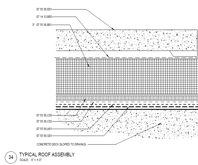
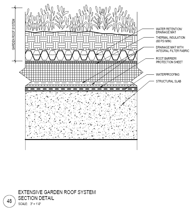
Figure 8 | Northwest Perspective | Courtesy of SmithGroupJJR
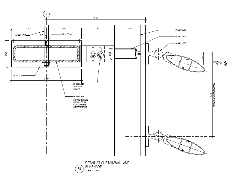
Figure 9 | Sunshading in Curtain Wall | Courtesy of SmithGroupJJR
Of the sustainability features included in the design of this building, the ones that are most apparent are
the photovoltaic panels on the main roof (1 above in Figure 8), the garden roof on the lower roof (2 above in
Figure 8), and the sun shading features on the South curtain wall façade. The photovoltaics, create energy for
the building’s use, provides a testing ground for the energy research that the school foresees in their future
and compliments the overall aesthetic of the building giving it an interesting and raw quality. The lower roof
garden will aid with the heating and cooling of the lab spaces below and also provide the students and faculty a
nice environment to walk around. The sunshades on the curtain wall façade on the South side of the building,
shown in Figure 9, will provide shading to the interior and let in a smaller portion of the total daylight into the
atrium space and also add another layer to the curtain wall aesthetic. The designers and construction
managers along with Oakland University are targeting a LEED Gold Certification upon completion of the
project and have outlined a plan so as to obtain this.
_withNumbers.jpg)
building statistics | part 2
construction |
Walbridge Aldinger Company was the construction manager at risk for this project. They started work in the construction in January of 2013
and finished up construction in late August of 2014 opening the Engineering Center for use in the fall 2014 semester. As part of the
construction of this new facility for the School of Engineering and Computer Sciences, they also renovated 15,000 square feet of space in
other buildings that the SECS previously occupied on campus.
Utility power, at 13.2 kV, enters the building on the ground level into a designated substation room. The substation room contains two
transformers taking the voltage down to 480Y/277V power, which travels through feeders to the electrical rooms on each level and multiple
480/277V panels in the substation room. There are designated electrical rooms on every floor including the penthouse level. Within each
electrical room are step-down transformers from 480Y/277V power to 208Y/120V which supplies the power to branch panelboards powering
the receptacles, mechanical equipment, and some lighting.
The emergency power is supplied by a 225A natural gas generator in the penthouse provides the power to the fire pump controller from a
480Y/277V panel. Two turbogenerators are also located in the penthouse and provide the power to the other necessary amenities for life
safety including emergency lighting, elevators, stair pressure fans, lab and atrium exhaust fans, sump pumps, atrium coiling doors, and the
other loads on the legally required panels.
The lighting design for the Engineering Center is energy efficient, functional, fairly minimalistic, and pleasingly accents the architecture of
the spaces. Each space was evaluated both quantitatively and qualitatively to provide the building with a solution that works with the
architecture and provides quality lighting. The building primarily uses LED and linear fluorescent fixtures. The spaces with one or two main
tasks are simpler in design and contain a minimal number of fixture types. Those that are more public and more complex, in terms of task,
have more complex and visually appealing lighting schemes with points of interest and layers of lighting.
A very important aspect of the lighting scheme is the use of controls. The larger classrooms are all equipped with Lutron lighting controllers
to provide zonal control and scene control of the spaces as well as interface with projector and projector screen control. Daylight dimming
photocell sensors are used throughout the building for lighting dimming purposes to save energy by supplementing daylight for electric
light. Combination occupancy/daylight/HVAC sensors are also used to turn on lights and HVAC systems when occupied as well as dimming
as daylight increases.
The air handling system for the Engineering Center comprises of one 5200 CFM capacity air handling unit in the penthouse of the building, a
30000 CFM make-up air unit on the roof, and a 30000 CFM heat recovery unit also on the roof. These units provide the required air
exchanges to all of the interior spaces through volume control boxes.
Cooling for the building uses two cooling towers, CT-1 and CT-2, rated 750 GPM each and an 8” main cooling loop servicing the building fan
coil units and chilled beams. If the system is in a heating mode, heat exchangers connected to the system provide cooling as well.
General building heating is provided by a low temp heat recovery boiler that recovers heat from the exhaust of the turbine generators. The
high temp heat recovery system also recovers the exhaust from the turbine generators and provides some heat to the building and some to
the campus high temperature loop.
A building management system, or BMS, controls the mechanical systems in the building through a central control.
The structure of the Engineering Center consists of a concrete foundation, steel framing structure, and composite decking for the floors and
roof. Foundations include 3000 PSF continuous footings, 35 PCF retaining walls, and 55 PCF basement walls. Structural beams are placed to
account for building dead and live loads as per code in a manner that does not detract from the building aesthetic. The column sizes vary in
size from W8x28 to W14x176 and are spliced for the longer column lengths. The composite slab typically consists of 2” depth 16 or 18GA
steel decking, 4.5” deep normal weight concrete at 4000-PSI strength, and steel reinforcing.
The most interesting structural challenge on this project was the cantilevered stair structure in the southern lobby space. Here the
engineers used an exposed beam structure to support the middle of the stair without detracting from the effect.
Fire protection is important for both the safety of the occupants as well as the building. The building is fully equipped, in accordance with
NFPA requirements, with smoke detectors, fire alarms and sirens, strobe lights, a sprinkler system, exit signs, fire-proofing, fire walls, and
lab and atrium exhaust fans. On the first level there is a designated fire pump room with a 480V, 3PH, 3W, 100HP fire pump and a 480V,
3PH, 3W, 2HP jockey pump as well as a fire pump controller with wye-delta starter and integral automatic transfer switch. The systems
necessary for life safety and code are all included on the emergency power.
There are three elevators servicing the building and transporting occupants to all levels of the Engineering Center. Elevator #1 is 30HP and
is controlled in room 100A. Elevator #2 is 30HP and is controlled in room 100B and elevator #3 is 45HP and is controlled in room 153A;
elevators #2 and #3 are included in the emergency power scheme.
Another transportation related device in the Engineering Center is a wheelchair lift located in the 200-seat lecture hall and provides disabled
individuals access to the bottom tier of the lecture hall.
The Engineering Center uses many different telecommunications systems to be the most state-of-the-art a facility as possible. CATV and
CCTV cables service the building’s video surveillance and television systems. Each of the classroom spaces house projectors, projector
screens, central control systems, video cameras, and audio speaker systems. Certain rooms and the building entrances require card reader
access so as to keep the facilities safe. This facility is certainly equipped for the future for the School of Engineering and Computer
Sciences.
email | jdc5349@psu.edu |