BUILDING STATISTICS


IPD/BIM TEAM #3
CLASS OF 2011

   
General Statistics | Architecture | Building Enclosure | Sustainability | Construction | Electrical | Mechanical | Structural | Additional Support Systems

GENERAL BUILDING STATISTICS

For a digital copy of the building statistics, click here.

Overall Data
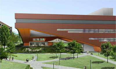
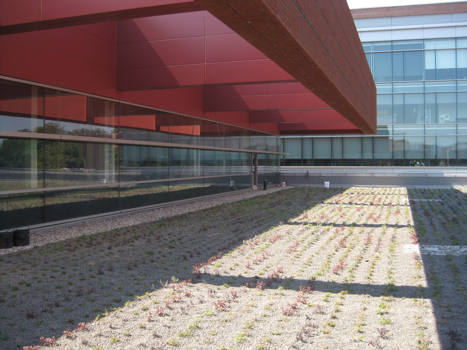
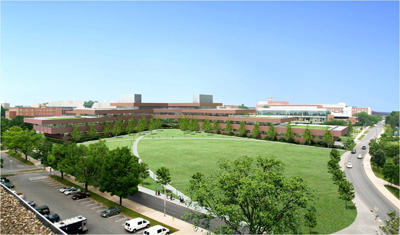
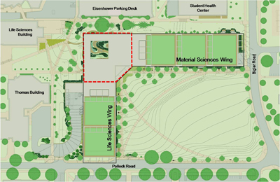
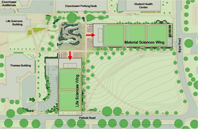
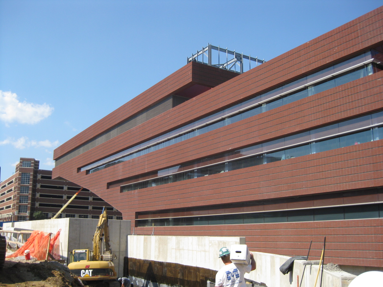
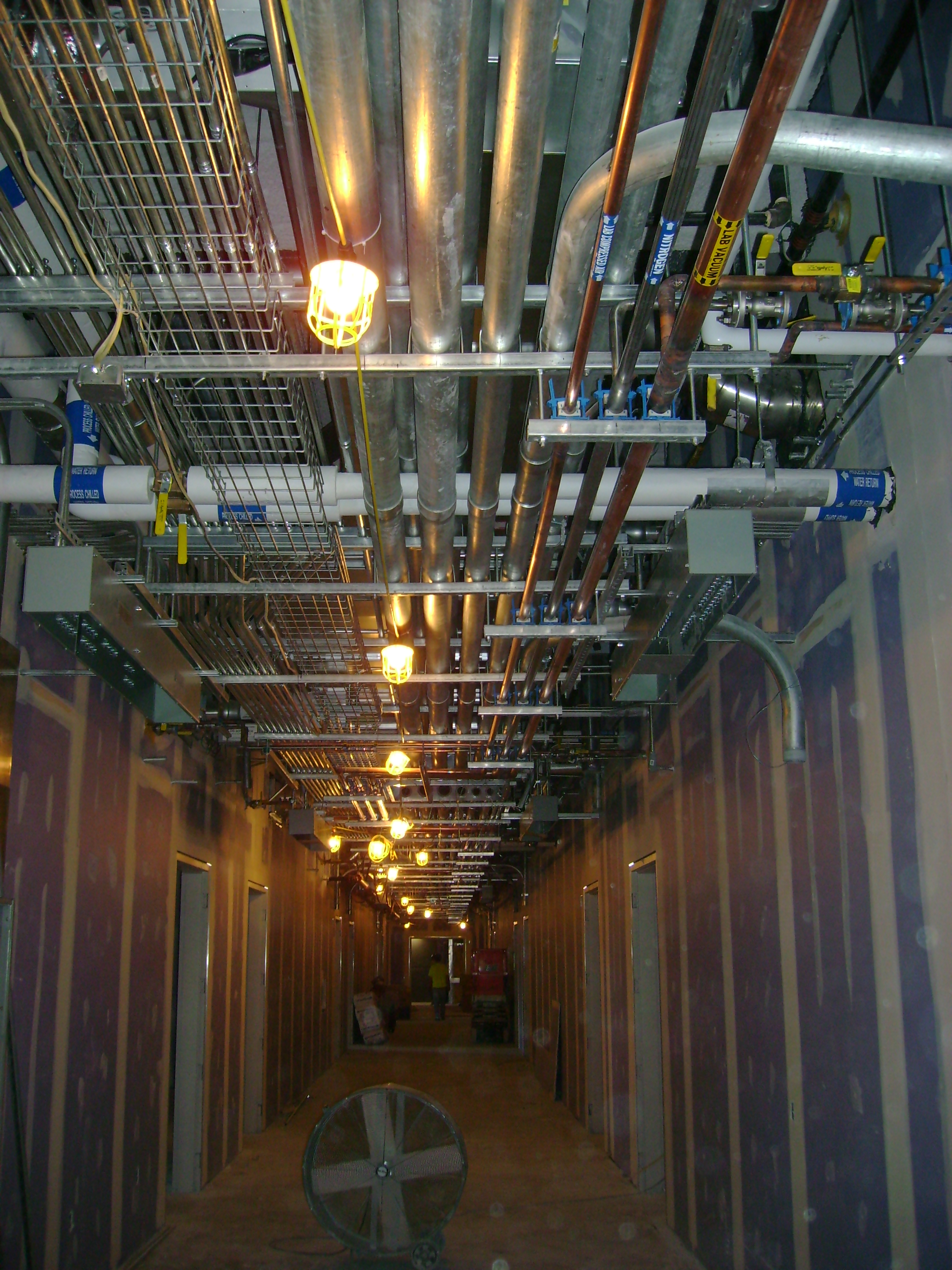
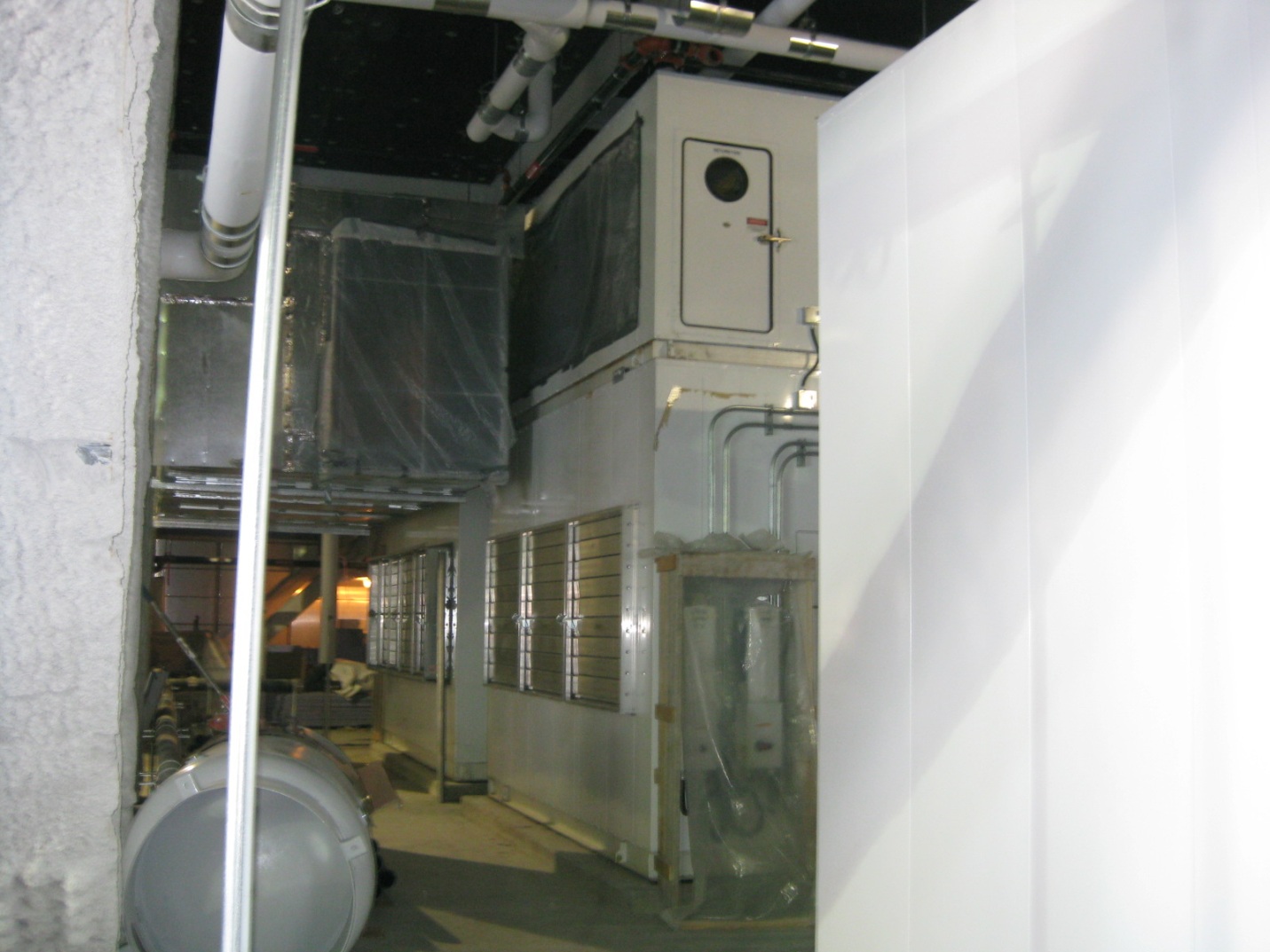
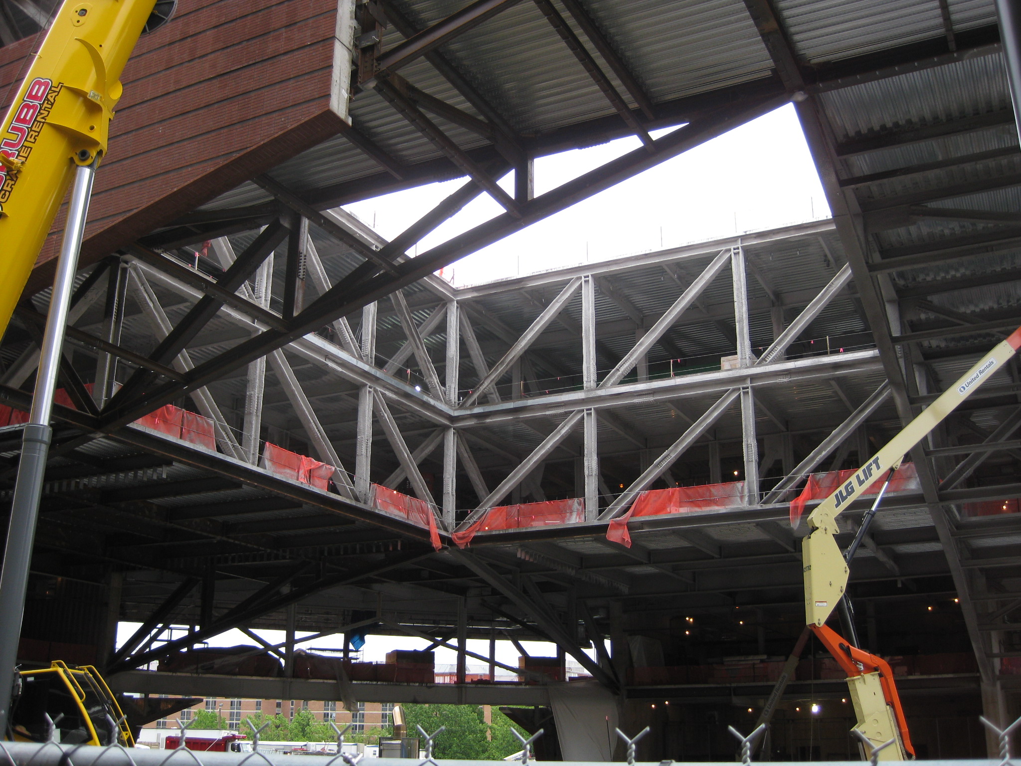
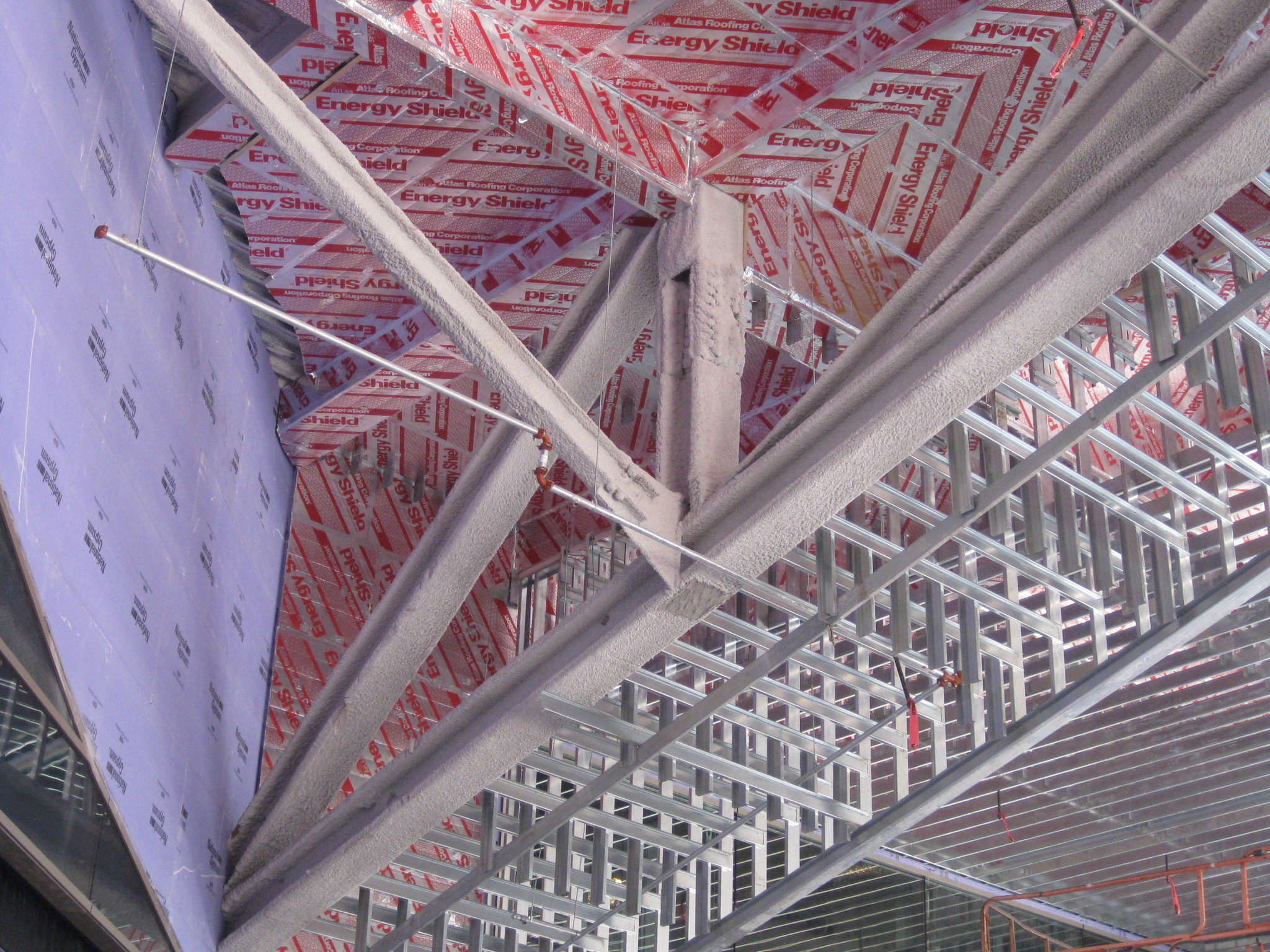
Building Name: Millennium Science Complex
Location: University Park, PA
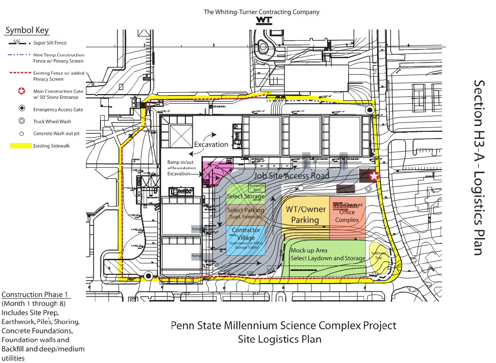
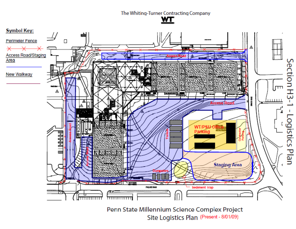
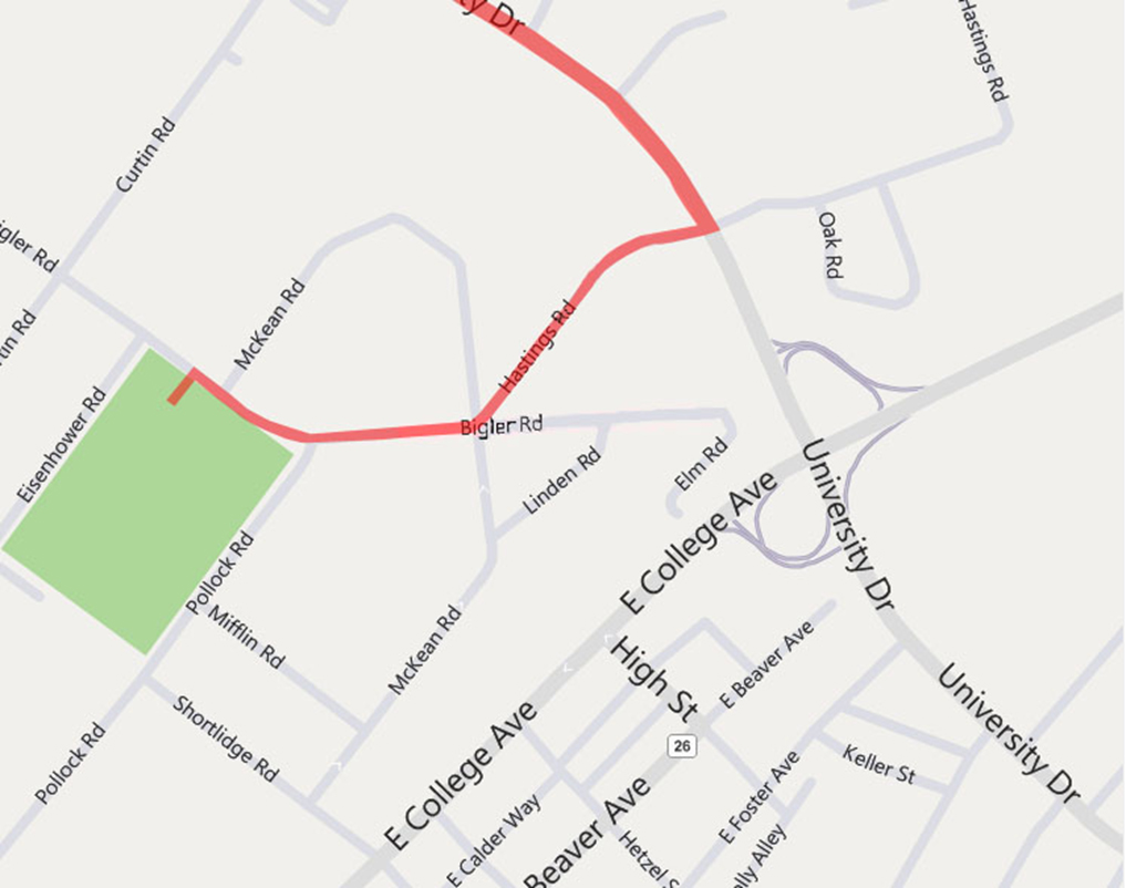
Site: Corner of East Pollock Rd. and Bigler Rd.
Occupant: Penn State Office of the Physical Plant
Size: 275,600 SF
Floors: Three above grade, penthouse, mezzanine, and basement
Use: Science research complex

Project Team
Owner: The Pennsylvania State University
General Contractor/CM:
Whiting Turner
Architect:
Rafael Viñoly Architects, LLC
Consulting Architect:
Perfido Weiskopf Wagstaff & Goettel
Structural Engineer:
Thornton Tomasetti Engineers
MEP Engineer:
Flack and Kurtz
Telecommunications: Shen Milsom Wilke
Acoustics/Vibration Consultant:
The Papadimo's Group
Lighting Consultant:
Brandston Partnership, Inc.
Landscape Architect:
Dewberry
Civil Engineer:
Sweetland Engineers and Associates, Inc.
Laboratory Planner: Steven Rosenstein Associates, Inc.
Vertical Transportation:
Van Deusen and Associates
Life Safety Code Consultant: Hughes Associates, Inc.
E.M.F. Consultant:
Vitatech Engineering
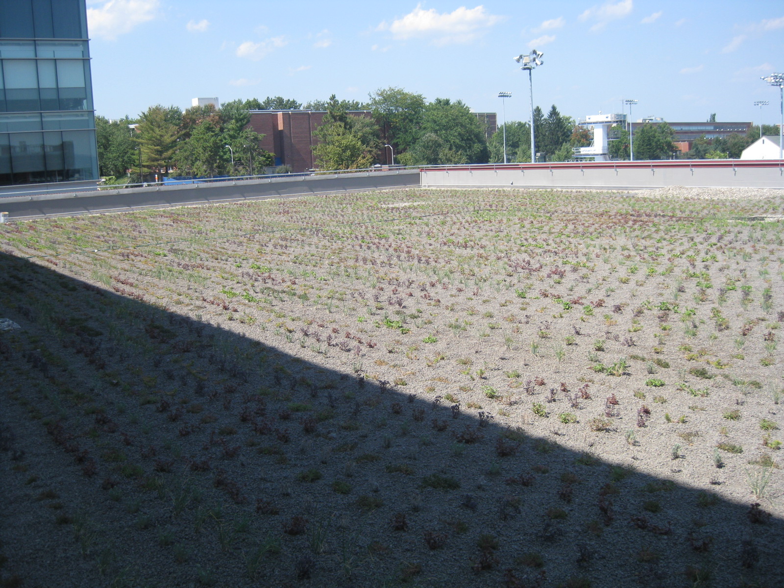
L.E.E.D. Consultant:
Rocky Mountain Institute
Clean Room Consultant:
IDC Architects, PC-CH2M Hill


Time and Cost
Delivery Method: Design-Bid-Build
Dates of Construction: June 2008 - June 2011 (proposed)
Overall Estimated Cost: $230,000,000 budgeted
Building Costs: $175,000,000


Zoning
The Millennium Science Complex is located within Subdistrict 5, which is in the central and southeastern parts of the University Park Campus.  This Subdistrict contains teaching and research facilities, as well as student services and housing. This Subdistrict has physical requirements that include the following:

- A maximum permitted density based on a FAR of 1.0.
- A maximum impervious surface coverage of 55%.
- A minimum open space of not less than 45%.
- A maximum height of 90 feet for any area more than 250'-0" from a District boundary
- A minimum building setback of 40'-0" measured from the curb


National Model Codes
IBC 2006
NFPA 70

Back to Top


ARCHITECTURE

The Millennium Science Complex is a 4-story LEED-Certified laboratory facility housing Life Sciences and Materials Sciences on The Pennsylvania State University, University Park campus.  Located on the eastern end of campus at the corner of E. Pollack and Bigler Rd, the Millennium Science Complex is an L-shaped building with stepping cantilevers and expansive green roofs.  Stepping green roofs allow for minimal intrusion on pedestrian areas while concentrating the heart of the building away from the street, maximizing green space.  Designed by Rafael Viñoly Architects the building was designed with continuous horizontal glazing along each floor creating a plethora of natural light.

The building is composed of two wings joined with a 150-ft cantilever that stretches out over an open air public plaza.  The cantilever allows for the addition of necessary isolated research laboratories to be located beneath the plaza without transferring vibrations through structural members.  Over the plaza the wings of the building join at the 3rd and 4th floor to create the L-shaped research facility.  The 3rd floor is composed of open meeting areas and lounge space, whereas the 4th floor is dedicated entirely to mechanical space.  Rafael Viñonly Architects have created a unique state of the art facility that compliments Penn State’s faculty while providing the tools for research in the field of life and materials sciences.

Back to Top

BUILDING ENCLOSURE

A complex pre-cast panel system comprises the majority of the Complex’s building enclosure.  Each of the 338 precast pieces were fabricated in York, PA and trucked to the site.  The exterior is clad in “Penn State” brick with bands of recessed dark-fired brick adhered to 6” of concrete.  This panel is backed by 4” of rigid insulation and a vapor barrier.  Each 22’ panel is mechanically attached to the exterior column structure by a threaded rod and gusset plate system.  Between each precast section, two lites of glass are broken by an exterior shading device, meant to help control solar heat gain and glare, while adding a valuable aesthetic feature.  The lower vision lite wraps around the entire building providing views to the exterior, while the upper lite is fritted and meant to improve day lighting.  A system of metal panels and storefront glazing encloses the building around the landscaped exterior atrium.

The roofing system, once designed to be the largest green roof in the United States, will span 60,000 sq. ft.  This extensive sedum green roof will require a shallow depth of soil and drainage, and will be waterproofed from the concrete structure below.  The mechanical penthouse will not have a green roof, rather it will be built of rigid insulation covered by a black EPM waterproofing membrane.

The vibration isolated laboratories located under the exterior atrium will be enclosed in a system unique to the building.  As these labs are located underground, they will be surrounded by concrete to mitigate sound and vibration transmittance, while providing moisture protection and thermal resistance.

Glass Curtain Wall - Clear Float Glass, Laminated Glass, Safety Glass

Roof – EPDM membrane, tapered rigid insulation sloped at ¼” per foot to drain

Roof structure – rigid insulation on concrete slab

Curtain wall system with solar shades

Back to Top

SUSTAINABILITY FEATURES

The Millennium Science Complex is designed to achieve LEED© Gold Certification by employing several sustainable features.  One of the most unique features is the extensive green roof located on both wings of the building.  It serves not only as a storm water control strategy, but also to reduce the building energy loads by acting as an insulator, extend the life of the roof, and filter pollutants and greenhouse gases from the air.  Storm water collected will be diverted to underground cistern and used for the site’s landscaping.  The Millennium Science Complex will be the third building on Penn State’s University Park campus to utilize a green roof system.  The remainder of the roof consists of white elastomeric sheet roofing which has a high reflectance and high emissivity to help reduce the thermal gradient.

During construction of the complex, almost 90% of the construction waste was diverted from disposal and at least 10% of the materials used were from recycled content, including the steel-frame, concrete, and precast concrete.  In addition to the recycled content, sustainably harvested wood was used for carpentry and 10% of the materials were regionally sourced. 
Throughout the interior, stringent criteria for low-emitting materials for adhesives, sealants, paints, coatings, and carpet systems were strictly enforced to promote indoor air quality.  Independent exhaust is provided for each laboratory, vivarium, and other rooms where hazardous gases and chemicals may be present to help ensure indoor air quality as well.  Carbon dioxide monitors are provided in all densely occupied spaces.

Natural daylight is provided extensively throughout the building, including the offices and laboratories due to the perimeter layout.  The interior architecture also allows the daylight to reach the hallways from the offices and laboratories.  Semitransparent glass, solar shades, and louvers are found throughout the entire façade to encourage daylight without heat gain or glare for optimal solar shading.  Individual lighting controls is provided for 90% of the building occupants as well as lighting controllability for shared spaces.  Advanced control systems are also designed for the management of the HVAC systems to emphasize energy efficiency.

Back to Top

CONSTRUCTION

The location of utilities is one of the main issues a construction team faces when building a new project.  The Millennium Science Complex contains a tunnel for transporting chemicals and materials between the Life Sciences Building and the Life Sciences wing of the Millennium Science Complex.  The phasing of this tunnel was extremely important because the pedestrian paths in this area are a main source of travel for students, and the location of the utilities were unknown, so excavation was closely monitored.  The construction of this tunnel consisted of three phases as seen in the images on the left.

The construction of the Millennium Science Complex was planned to be a two phase schedule, with the first phase being site preparation, earthwork, piles, shoring, concrete foundations, underground utilities, and backfill.  The second phase consisted of steel erection, superstructure concrete, roof, precast, building tight enclosure, interiors, MEP, and drywall.  Initial site logistics plans for both phase one and two can be seen to the right. However, as often happens with construction projects, the plans have been revised to further increase efficiency at the site.  The current, revised site logistics plan can be seen to the right.

Another major issue facing the construction team was how to bring materials and equipment into the site.  Because the site is located in the middle of the Penn State University campus, available space is at a premium.  The site did not offer much space for material storage, so materials were typically scheduled to be brought in the day it was required.  It was required that trucks were not to be driven through campus, so it was planned that the trucks would be brought in from University Avenue onto Hastings Road, which connects to Bigler Road and the construction site.  This path can be seen in the map to the right..

Back to Top

ELECTRICAL

Power Distribution
The electrical system for the Millennium Science Complex is a 12.47kV service feeding a set of dual 4000A, 480Y/277V switchgears (main-tie-main) through two pad mounted transformers. Distribution begins with 480Y/277V for lighting and other systems, then stepped down at further locations to 208Y/120V for receptacle and equipment power. Emergency power is fed from two separate switchgears which feed multiple ATS's with both normal and emergency power. To limit the EMF from interfering with sensitive equipment, electrical closets are encased with aluminum shielding and in certain areas rigid conduit is used in place of standard conduit.

Lighting
All lighting is on 277V service.  All building perimeter offices and laboratories are controlled by both occupancy and daylighting sensors with appropriate dimming ballasts.  Typical internal laboratory and office rooms are controlled by the occupancy sensor.   Three general types of ballasts are used.  Class B quiet dimming ballasts are used in the quiet labs.  Lutron's Hilume dimming ballasts are installed for rooms requiring less than 10% dimming from full power.  Advance Mark7 dimming ballast is used in rooms with regular dimming conditions.  A system of addressable ballasts is used in accordance with Lutron's GRAKIF Eye system.

Lightning Protection
The Millennium Science Complex is protected by Cooper Air Terminals in coordination with NFPA 780.  Air terminals located in spaces within the bounds of roof walls are mounted on bases provided by Cooper.  Cooper provides the grounding conductor, which is fastened by clips to the top of the perimeter walls.  Down conductors penetrate the roof and route behind the concrete panels of the façade in PVC conduit where they ultimately terminate at a ten foot ground rod.

Telecommunications
The telecom system consists of only a few major components – combination voice and data outlets, telephone outlets, and paging speakers.  The majority of spaces contain combination voice and data outlets prewired into furniture components.  Several voice/data outlets are located along all corridors and several locations have above-ceiling mounted telecom outlets for wireless access points.  All offices contain at least one quad outlet and one duplex telecom outlet, while conference rooms contain one wall-mounted duplex outlet and a floor-mounted quad outlet.  Computation/study areas and conference rooms also contain floor poke-through routing capability.  Basket-type, twelve inch by four inch, cable trays route telecom wiring throughout corridors.  Each floor is fed by several IDFs – two for the basement, four each for the first and second floors, and two for the third floor.  The telecom backbone consists of one 24-strand multimode, one 24-strand single mode fiber optic cable, one 50-pair CAT-3 UTP cable, and one RG-11 coaxial cable between the MDF and each IDF.  The telecom system is grounded through the telecommunications main grounding bus bar back to the building electrical ground.

Fire Alarm
The Millennium Science Complex fire alarm system was designed in accordance with NFPA 72. The fire alarm system consists of audio, visual, and combination audio/visual notification devices. Activation devices consist of smoke detectors, heat detectors, and fire alarm pull stations. The system also contains tamper and water flow switches in the stair wells.  The systems Fire Alarm Control Panel is located in Receiving N-041.

Security System

The security system was designed in accordance with NFPA 70, NFPA101, and NEC. The system consists of magnetic swipe card access with electronic strike, door contacts, and request to exit. Exterior doors, and egress stairwells have local audible alarms. Access control panels, along with class “E” fire alarm relays are located in the security/telecom closets. Millennium Science Complex also has a CCTV system consisting of fixed type cameras. All data recorded are stored on a Digital Video Recorder in LS/MS Server Room N-020.

Back to Top

MECHANICAL

Mechanical System
The Millennium Science Complex combines both Materials Science and Life Sciences functions and spaces into one building.  Each of these spaces contains offices, laboratories, and unique rooms such as a vivarium and a clean room.  Different HVAC strategies are required to handle the varying requirements of this unique building. 

The Millennium Science Complex connects into the existing campus steam lines and chilled water lines.  Steam enters the building at high pressure, 140 psi, but requires two pressure reducing stations to reduce the steam pressure to medium and low pressures of 60 psi and 15 psi respectively.  Medium pressure steam is utilized for sterilization, heat exchangers, and other equipment loads.  Low pressure steam is used for the steam coils within the AHUs and in heat exchangers that produce hot water for use in reheat-coils at terminals devices.  

Chilled water is pumped throughout the building using three (3) variable speed split case pumps, with one reserved as a standby.  An auxiliary low flow pump is utilized for part load conditions.  The AHUs that serve the animal care facility and main lab are connected to standby power to allow for cooling of these spaces during the loss of power.

The laboratory areas of the building are served by five (5) 50,000 CFM VAV AHUs.  Each of these AHUs contains a supply fan, cooling coils, heating coils, humidification equipment, and MERV-14 filters.  All laboratory AHUs deliver 100% outside air.  In an effort to save operating cost and energy in the DOAS systems, general laboratory exhaust air enters an enthalpy wheel with the incoming supply air.  The laboratory fume hood exhaust is not included in the enthalpy wheel due to the potential contaminants within the exhausted fume hood air. 

The office, lobbies, and common areas are served by three (3) 40,000 CFM VAV AHUs.  These AHUs do not provide 100% outdoor air and instead contain a mixing box with CO2 sensors in the outdoor air, return air, and all conference rooms to ensure that the CO2 concentrations in these areas is maintained at appropriate levels by supplying enough outdoor air.
More specifically, the animal care facility is served by two (2) 25,000 CFM 100% outdoor air units.  Each unit is sized to handle the full load of the space.  The redundancy is needed to allow for continual service to the animal holding rooms and the rest of the animal facility should one unit fail.  The clean room also has its own AHU that is designed to maintain the room’s humidity levels at 45% RH.  The animal care facility AHUs, quiet lab AHU, and clean room AHU all utilize run around heat recovery coils in an effort to reduce energy usage.

In addition to the main AHUs, cabinet unit heaters, electric heaters, fan coil units, supplemental air conditioning units, and other local equipment are used to address areas of the building where the main HVAC equipment cannot feasibly serve the area.  It is necessary to have all of the previously mentioned components in order to effectively keep the building operating under optimum conditions for the various building occupants.

Fire Protection
The Millennium Complex will be protected on all floors by an automatic fire alarm notification system.  Manual pull stations will not be required where the alarm notification appliances activate upon sprinkler water flow in this fully sprinklered building.  The First Floor Outdoor Plaza must also be fully sprinklered as there is potential for combustible materials to be handled under the canopy.  The laboratories will be designed to meet Ordinary Hazard Group 1 or 2, while storage rooms with dispensing capabilities must be designed to Extra Hazard Group 2. 

An automatic standpipe system will be required throughout the building, and hose connections will be required on each floor at an intermediate landing level in stairways.  A minimal residual pressure of 100 psi is required at the outlet of the hydraulically most remote 2 ½ inch hose connection.

Back to Top

STRUCTURAL

The sub structure is a cast in place reinforced concrete system consisting of localized groups of 7 in. diameter micro-piles, of ranging depths, under individual pile caps ranging from 36 to 72 inches in thickness and located at the intersection of the column grid lines. 24 and 36 in thick grade beams connect these pile caps along the grid lines.

The super structure consists of a typical steel framed building with regular 22 feet square bays. The average floor to floor height is 19 feet.   The typical construction for the two wings consists of steel wide flange columns and a concrete on metal deck floor system supported by steel wide flange beams and girders. Typical column and beam sizes range from W14X43 to W14X233 and W21X44 to W27X84, respectively. The typical floor system consists of 3 inch metal deck with 3 ¼ inch concrete topping.

The structure has to support the 150 foot cantilever at the intersection of the two wings. This is done through the use of a truss system consisting of wide flange members ranging from W14X90 to W14X283. This system is integral with a concrete shear wall extending from the foundation to the fourth floor level. This large c-shaped shear wall also contributes to the lateral force resisting system along with two moment frames and two smaller concrete shear walls at the stair wells.

Back to Top

ADDITIONAL SUPPORT SYSTEMS

Conveying Systems
Each of the two cores of the building houses both passenger and freight/service elevators.  Passenger elevators are either thirty or forty horsepower and require 130 FLA or 165 FLA respectively when accelerating.  The service elevators are seventy-five horsepower and operate at 300FLA when accelerating.  Passenger elevator requirements include 4,500 lb. carrying capacity and 200 fpm speed while service elevators are required to perform with 15,000 lb. carrying capacity and 150 fpm speed.

Back to Top


| SENIOR THESIS | THE PENNSYLVANIA STATE UNIVERSITY | ARCHITECTURAL ENGINEERING | AE LAB | CONTACT THE TEAM |

This page is continuously updated by this BIM/IPD group and is hosted by the AE Department (C)2010

Note: While great efforts have been taken to provide accurate and complete information on the pages of CPEP, please be aware that the information contained herewith is considered a work-in-progress for this thesis project. Modifications and changes related to the original building designs and construction methodologies for this senior thesis project are solely the interpretation of this BIM/IPD group. Changes and discrepancies in no way imply that the original design contained errors or was flawed. Differing assumptions, code references, requirements, and methodologies have been incorporated into this thesis project; therefore, investigation results may vary from the original design.