Building Name
Fort Detrick Defense Medical Logistics Center
Location and Site
Porter Street
Fort Detrick, Maryland 21702
Frederick County
Building Occupants
The top nine medical planning organizations within the Department of Defense representing the Army, Navy, Air Force, and Marines
Occupancy or Function Types
Office
Size (Total Square Feet)
129,960 Square Feet
Number of Stories above Grade / Total Levels
Three (3)
Dates of Construction
September 15, 2006: Site Mobilization, Demolition
April 22, 2008: Projected Finish
Cost Information
$26.5 Million firm-fixed-price
Project Delivery Method
Design-Build
Owner
United States Government / Department of Defense
Owner Representative
U.S. Army Corps of Engineers – Baltimore District
General Contractor and Construction Manager
Mascaro Construction
Architect
Renz Weinmann
Baker and Associates
Civil Engineer
Joe Blickenderfer
Baker and Associates
Structural Engineer
Rich Hoadley
Baker and Associates
Mechanical Engineer
Dennis Myer
Baker and Associates
Electrical Engineer
Tom Basch
Baker and Associates
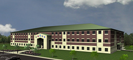
Design and Functional Components
This building is a large, modern administration and support building with a postmodern design influence. The building’s exterior is massed to divide the building into three sections: base, middle, and top. This is accomplished through variation in exterior building materials and windows. The building is also characterized by a pitched roof and masonry exterior. Two entries are located at the centers of each of the long sides of the building to admit pedestrians and building users dropped off at a front drive as well as the rear parking lot. Upon entry, users pass through a central corridor accessing elevators, stairs, and central toilet facilities. This center passage includes a two-story atrium between the first and second floors.
Major National Model Code(s)
Unified Facilities Criteria (UFC)
IBC 2003
National Fire Protection Association (NFPA)
ADA and ABA Accessibility Guidelines
Uniform Federal Accessibility Standards (UFAS).
AT/FP – Anti-Terrorism/Force Protection
Zoning
The building is classified as Business Group B in the International Building Code. It is a commercial office building that will reside on the Ft. Detrick Military Base. Site limitations are as follows:
Maximum allowable height: 4 stories (actual: 3 stories)
Maximum allowable area: 86,250 SF/floor, 258,750 SF total (actual: 43,320 SF/floor, 129,960 SF total)
Building envelope including description of roofing system and all the various types of exterior wall systems used throughout the building:
The exterior wall system is non-load bearing brick veneer with insulated metal stud backup. Floor to floor height is fourteen feet, with ten feet from third floor to bottom of roof trusses. Brick is the main element of the façade with stone accents at window and lintels. A stone base is included at the first floor. The roof is a gable-style, metal system at a 3:12 slope with metal gutters and downspouts and soffit and fascia trim. Exterior windows are bronze anodized aluminum with insulated glazing. Exterior entry door openings are bronze anodized aluminum frame door systems. Exterior service door openings are painted hollow metal doors and frames. All exterior windows have laminated glass at the interior pane for AT/FP criteria. Insulation for the building envelope was designed to comply with ASHRAE Standard 90.1, Chapter 5.
Construction
Ft. Detrick is a design-build-project with a $26.5 million firm-fixed-price. The building is owned by the U.S. Department of Defense. The contract is structured so that the owner representative and construction manager/general contractor are in contract with the owner. Since it is a design-build project, the architect and engineers are in contract with the construction manager/general contractor. Construction started with site mobilization and demolition on September 15, 2006. Important milestones include the completion of foundations on February 15, 2007, completion of concrete slabs on June 4, 2007, expected date of building enclosure on January 14, 2008, and expected date of completion on April 22, 2008.
Mechanical System
Ft. Detrick contains six air-handling units (AHU-1 through AHU-6) that are on during regular operation and one emergency air-handling unit (AHU-7) that runs by generator power. All units supply a mixture of outdoor and recirculated air to multiple zones. Each floor has 2 mechanical rooms, one on the north end and one on the south end, where an air-handling unit is housed. The emergency unit is on the south end of the second floor and serves the Joint Operations Command (JOC) office area if the power to AHU-4 goes out. There is a separate mechanical room located on the south end of the first floor that houses the boilers, chillers, and pumps. All AHUs are controlled by variable frequency drives (VFDs) and distribute air through variable air volume (VAV) hot-water reheat boxes. In this design, each zone can adjust individually to the desired airflow. Spaces not served by the air handlers include stairwells, vestibules, mechanical rooms, communications rooms, and restrooms. Stairwells, vestibules, and mechanical rooms are heated only and are served by electric cabinet unit heaters. Communication rooms house servers and other electrical equipment. They are cooled only and are served by air conditioning units in each room. Restrooms are heated and cooled by transfer air. The chiller plant contains two rotary screw water-cooled chillers at 220 tons each, which supply AHU-1 through AHU-6 with chilled water. AHU-7 is self-contained. The chillers are also controlled by VFDs on the pumps. Condenser water is evaporatively cooled via two induced-draft cooling towers, each with two speed fans. Chillers and towers are linked to permit either tower to serve either chiller. The boiler plant includes two gas-fired hot water boilers at 2160 MBH each, which provide hot water to AHU-1 through AHU-6, VAV reheat coils, and unit heaters. The hot water is distributed using a reverse return loop on each floor. The boilers have modulating burners that are each sized for 65% of the peak load. The boilers, too, are controlled by VFDs on the pumps.
Electrical System
The electric service comes from a new 4160V overhead distribution line delivering power to the facility power transformer. Electric distribution inside the facility consists of two different voltage systems. A 480Y/277 volt, three phase, four-wire system with a neutral is used for lighting and HVAC loads. A 208Y/120 volt, three phase four-wire system with a neutral is used for offices, general-purpose receptacles, computers, and miscellaneous small loads. An automatic transfer switch and exterior power outlet provide means to connect to standby power.
Lighting
Linear fluorescent lamp type light fixtures with electronic ballasts and T-8 lamps are located in all interior areas with grid ceiling. Down lights with a compact fluorescent lamp are used to accent and or supplement other lighting. A battery pack provides emergency lighting. Dual switch, automatic dimming, manual dimming or occupancy sensors (in public areas) are used throughout for energy conservation. Exterior building lighting is provided at roadways, pedestrian walkways, and steps.
Structural System
The foundation system consists of reinforced cast-in-place concrete grade beams supported by reinforced concrete caissons with bells. Caissons range in diameter from 24” to 30” and also support the interior steel columns. The bells are typically twice the diameter of the caissons. Above grade, the facility is supported by a steel framed system with concrete floors. The steel joists are spaced at approximately 5’-0” on center and are supported by steel girders and columns. The typical floor framing of the structure consists of 2“ - 20 Gage composite metal deck with 2 ½” of normal weight concrete topping resulting in a 4 ½” thick slab. Steel beams that frame into girders and columns support the composite floor slab. A typical column bay is approximately 40’-0” x 30’-0” and beams in the bay are spaced at 7’-6” on center. The roof structure consists of a standing seam metal roof supported by metal roof deck spanning between steel joists.
Fire Protection System
Ft. Detrick DMLC is equipped with an automatic wet-pipe sprinkler system in order to meet the Department of Defense Minimum Antiterrorism Standard. The majority of the building falls under the “light hazard” design classification. Exceptions include storage rooms, mechanical rooms, and electrical rooms, which are classified as “ordinary hazard.” The building is split into six zones (in the same way it is divided for the six air handling units), and each zone is served by its own sprinkler-piping loop. The loop starts and ends at the stairwell adjacent to the exterior wall, and each loop has its own inspector’s test station. A fire alarm system is also incorporated throughout the building. In addition, walls, partitions, floors, floor-ceiling assemblies, and roof-ceiling assemblies have a one hour fire rating.
Transportation
There are two elevators conveniently located at the end of the entrance vestibule, with a staircase across the hall. There are also two more staircases, one on the north end of the building and one on the south end.
Telecommunications
Ft. Detrick has six IT/Communication rooms, two on each floor. They are stacked vertically on top of each other to limit the travel distance of the wires. The main service entrance communications room is on the south end of the first floor and connects to the other communications rooms through a vertical riser cable. Each Communication room has two equipment cabinets, one for voice and one for data. Each workstation/office has one voice and two data duel gang boxes. A single gang outlet box for voice is in each electrical, communications, elevator equipment, and mechanical room and outside each door. The Joint Operations Center (JOC) on the second floor has all outlets, cable, raceway, wiring devices, and associated hardware for a Secret Internet Protocol Router Network (SIPRNET) system. In addition to the telecommunications infrastructure of each workstation, the JOC workstations have a duplex single mode fiber optic cable outlet.
|