Army National Guard Readiness Center Building Statistics
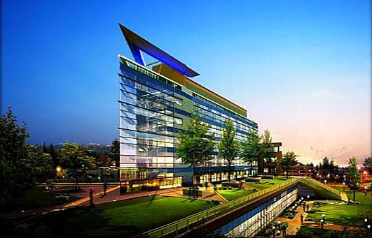 Figure 1 - Army National Guard Readiness Center Figure 1 - Army National Guard Readiness Center |
|---|
Part 1: General Building Data
Building Name:
Army National Guard Readiness Center
Building Location:
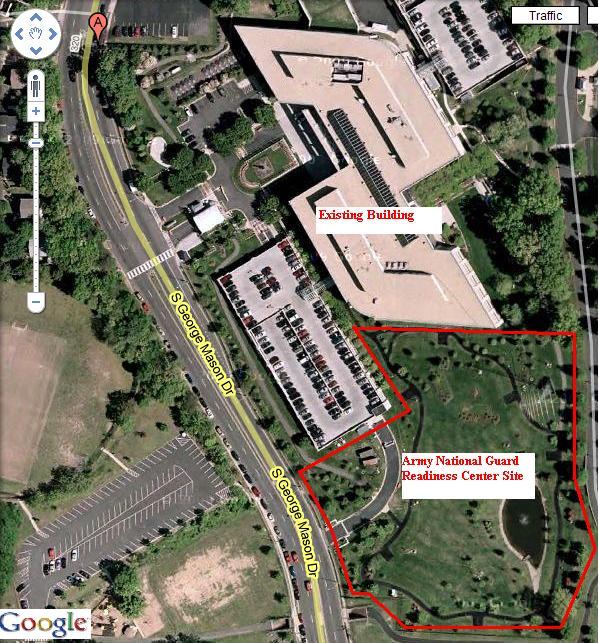
The project is located in Arlington, VA. The Army National Guard has an existing building on site and this project is an expansion of that building. It is a free-standing building but will be connected to the existing building by a bridge spanning the gap between the two buildings on the north side of the new structure and the south side of the existing building.
Building Occupant:
Army National Guard
Function:
Federal office/administration building for the Army National Guard.
Size:
251,444 sf office building and a 435 space parking garage
Stories:
Number of stories above grade/total floors: Office building is 3 stories below grade and 5 stories above grade. The parking garage is 3.5 stories below grade and 1.5 stories above grade.
| Project Team |
|---|
Owner: Army National Guard
|
General Contractor: Tompkins Builders Inc
|
|---|---|
Architect: CH2M Hill
|
Engineer: AECOM
|


Dates of Construction:
Start Date: December 1, 2008
Completion Date: March 1, 2011
Cost Information:
Direct Costs: $86 million
Indirect Costs: $9.5 million
Current Total Project Cost (after approved changes): $98.3 million
Project Delivery Method:
Design-Bid-Build with General Contractor holding Lump Sum contracts with subcontractors.
Architecture:
Design and Functional Components: This building will function as an administrative headquarters building being constructed as an addition to the existing building on site. The 3 largest stories of the building are below grade and hold open office space, a Joint Operations Center, fitness facilities, locker rooms, and an auditorium. Once above grade, the building footprint gets smaller and climbs 5 stories into the sky as a triangular tower. The tower floors function as general office space, conference rooms, and a small library. The transition between the 3 lower floors and the tower forms a large outdoor plaza area with seating, walking paths, and will double as a green roof.
A unique feature of the building, added as a bid option, is a large steel tricorn (see rendering) sitting atop the southern point of the triangular tower. This architectural feature is purely aesthetic and is meant to give the appearance of an “eyebrow”.
There is a new parking garage being built on another part of the site, as well. The garage consists of 3.5 stories below grade and 1.5 stories above. It will tie into the existing parking garage and the elevations of the new garage are being designed to match those of the existing garage.
Major National Codes:
- International Building Code 2006
- Unified Facilities Criteria
- NFPA
- PAM 200-1, 415-15, 420-7
- LEED-NC v2.2
Zoning:
Research in progress...
Building Enclosure:
The tower portion of the building is enclosed in a mixture of class, metal panels, and architectural precast panels. Glass type has not been finalized and has yet to be submitted. The rendering below shows the layout of the various types of enclosure materials.
The roofing system consists of a vapor barrier on top of the structural concrete slab, sloped rigid insulation, a single-ply roofing membrane, and topped by roof pavers in certain areas. The plaza roofing system, doubling as a green roof, consists of: structural concrete slab with a softer concrete topping sloped for drainage, roofing membrane with fabric reinforcement, root barrier, insulation, a drainage water retention element, filter fabric, and finally a planting element.
Sustainability Features:
The plaza space that doubles as a green roof, as mentioned above, can be clearly seen in the above rendering. This is the most prominent sustainable feature for the project. There is no natural ventilation or solar shading associated with the building.
This project is still in the early stages of construction and many of the materials and products used in the building have yet to be submitted and finalized. More information will be included here at a later time. (Research still in progress.)
Part 2: Primary Engineering Systems
Construction:
The Army National Guard Readiness Center construction began on December 1, 2008 and is scheduled for completion on March 1, 2011. The contract is lump sum/design-bid-build and the general contractor for the project is Tompkins Builders Inc. The construction of the new parking garage and main building are going on at the same time on different areas of the site, so extensive coordination between Tompkins and it’s subcontractors is needed to coordinate progress being made on both areas of the site every day. The site is small and congested so it is necessary to plan out activities far in advance so that the space can be made for each task. Site logistics planning is critical to the success of the project throughout each phase of construction.
Building Information Modeling (BIM) is being used for coordination of the mechanical, electrical, plumbing, and structural systems in the building. The goal of BIM is to reduce the cost and schedule impact of the coordination process.
Electrical Systems:
Power comes into the site at 35.4kV, supplied by the local power company. ArNG has a switchgear which steps it down and feeds power into the building with 2 medium voltage feeders at 15kV each. These feeders connect to substations within the main building, where power is stepped down again to a 480/277, 3 phase, 4 wire system. Lighting systems are fed by 208/120, 3 phase, 4 wire panelboards.
Two 1500 kW diesel-powered generators located on the roof penthouse level supply emergency power to the substations located on the lower level. A large conduit riser goes down 7 stories through the building and cuts east-west across the second story to connect to the substation room.
Lighting: ArNG will be lit by fluorescent lamps (277V) and incandescent lamps (120V). Programmable lighting relay systems will control all of the open office areas. Dimmable lighting fixtures are provided in some of the smaller offices around the perimeter of the Operations Center. Automatic controls will cover the rest of the lighting.
Mechanical Systems:
A hydronic HVAC system, consisting of a four-pipe heating and chilled water systems, distribute water to the air handling units (AHU) and variable air volume (VAV) terminal units on each floor and the energy recovery units in the mechanical penthouse. AHUs and VAVs are supplied by outdoor air and individual units are regulated by a Building Automation System (BAS). The BAS controls individual units, monitors temperatures in each space, and controls the fan coil units (FCU) around the building, as well.
Each floor has a mechanical room where AHUs are located with individual VAVs and FCUs spaced throughout the floors. On the roof there is also a mechanical penthouse that houses emergency backup generators and the energy recover units.
Structural Systems:
The structure for this project is a mixture of Cast-In-Place (CIP) concrete and structural steel. Structural steel is being used for the southern stair of the above-ground tower. The rest of the building is CIP concrete. The walls are designed to be laterally braced by the floor and roof systems and shear walls located throughout the building provide extra lateral support.
Typical bay size varies from 20’x25’ to 20’x30’. Typical column size is 1’-10”x1’-10” with (8) #8 vertical reinforcement bars and #3 horizontal ties at 12” o.c.
Structural steel at the stair tower is HSS type beams and columns. Rectangular beams are either HSS12x8x.625 or HSS14x4x.625 while columns are composite round HSS8.625x.322 or HSS11.25x.500.
The foundation is a mat slab foundation system. It is a system whose strength is built around having multiple layers of reinforced concrete and stone to provide necessary compressive strength. The foundation system structural layers are as such: 6” crushed stone base, 2” mud mat, 3’-7” mat foundation, 2’-9” aggregate, and a 12” slab-on-grade.
The garage is Cast-In-Place concrete exterior walls and slab on grade with structural precast columns and driving surfaces. A unique feature of this project appears at the garage: a secant-pile wall permanent excavation support. The secant-pile wall is placed between the new garage and the garage existing on site. Due to the close proximity of these two structures to each other and the depth of the excavation for the new garage, a more advanced excavation support system was needed than the standard lagging.
Support Systems
Fire Protection Systems:
The sprinkler system is supplied by two hydrants providing a 1520 GPM flow rate. These hydrants are supplied by waterlines that are tapped into the existing water main on the nearby street. The building will employ both a Light Hazard, providing 0.10 GPM over 3000 square feet, and an Ordinary Hazard system, providing 0.20 GPM over 3000 square feet.
The main server room in the building employs a FM-200 system. FM-200 is a colorless, non-toxic gas that is stored in two 300 gallon cylinders which will release into the room and extinguish a fire within 10 seconds of detection. It is a clean product that will only minimally damage the equipment in the server room compared to a sprinkler system employing water, which will destroy the electrical components.
Transportation Systems:
There are two elevator cores in the building, one per major section of the building, with three elevators in each core. One of the elevators in core 1 was added later as a bid option. Elevators 1-3 (core 1) are rated for 3500 pounds and elevators 4-6 (core 2) are rated for 4500 pounds. Both elevator cores run all the way up the building, from the lowest subgrade floor to the top of the tower. All six elevators are finished with stone flooring for aesthetic purposes.
Three stairwells are located throughout the building. The main stairwell is located in the center of the building and services all floors, from Level 3P (the lowest level below grade) up through Level 5T (highest floor in tower). There is also a stairwell in the northwest corner of the building that runs from Level 3P up to Level 5T. Both of the tower stairwells are located at points of the triangular tower and the main stairwell, once it reaches grade, is enclosed entirely by glass, providing a striking view of the plaza space below. A stairwell in the southwest corner services the three levels below grade.
Telecommunications Systems:
There is a wide range of telecom equipment being installed in this building. All telecom systems will be fed through floor boxes installed in the access flooring system (see below). Numerous amounts of 4” conduit run throughout the building with at least two IT/COMM rooms per floor. The largest amount of conduit runs above the ceiling on the lower levels.
Special Systems:
-
100% access flooring in all IT/COMM rooms, conference rooms, and open office spaces. This simplifies the coordination process by supplying more space outside of the above ceiling space to run electrical conduit to provide more room for ductwork and piping above the ceiling. There is limited above ceiling space in this building so anything that can be taken out and located somewhere else is a huge benefit to the coordination process.
-
Blast requirements are built into many of the façade materials and exterior elements of the building. Blast rated class and architectural precast panels are located on the lower floors of the tower and there is a large berm sloping up to the plaza space all the way around the building to protect against vehicles loaded with explosives.