High School Capstone Project | Maryland Brady Sheerin | Construction Management |
||||||||||||||||||||||||||||||||||||||||||||||||||||||||||||||||||||||||||||||||||||||||||||
| Home | Student Biography | Building Statistics | Thesis Abstract | Tech Reports | Thesis Proposal | Final Report | Presentation | Reflection | e-Studio | ||||||||||||||||||||||||||||||||||||||||||||||||||||||||||||||||||||||||||||||||||||||||||||
|
|
BUILDING STATISTICS PART 1 GENERAL BUILDING INFORMATION Building Name: Cannot Disclose PRIMARY PROECT TEAM
Architecture – Design and Functional Components This project entails the demolition of an existing high school built in 1959, and the construction of a new state of the art school with a capacity of 1,200 students. The new building is located within close proximity of the present one so that it can be tied into the existing gymnasium. The new three story building consists of two, three story classroom wings, a connecting atrium, an auditorium, cafeteria, administrative offices, culinary labs, and auxiliary gym facilities connected to the existing gym which was finished in 2003. In the heart of the building is a large rotunda and spiral stair case topped with a curtain wall that creates a nice architectural feature for the building. Typical finishes consist of painted CMU and abuse-resistant gypsum drywall, tile, resilient flooring, and acoustical tiled ceilings. Architecture – Codes & Zoning Requirements Code: Zoning Requirements:
Building Enclosure Building façades
Sustainability Features This project has been designed to achieve a LEED Gold rating by acquiring no less than 39 points under the US Green Building Councils LEED® Green Building Rating System ™ for New Construction. The majority of the projects points will be coming from Sustainable Sights and Indoor Environmental Quality. Several ways this rating will be achieved is by focusing on alternative transportation, water efficiency, reducing the heat island effect of the roof, recycling/managing construction waste, and using Low-Emitting Materials. However the building falls short of capturing any points for day lighting and renewable energy.
|
||||||||||||||||||||||||||||||||||||||||||||||||||||||||||||||||||||||||||||||||||||||||||
BUILDING STATISTICS 2 |
||||||||||||||||||||||||||||||||||||||||||||||||||||||||||||||||||||||||||||||||||||||||||||
CONSTRUCTION |
||||||||||||||||||||||||||||||||||||||||||||||||||||||||||||||||||||||||||||||||||||||||||||
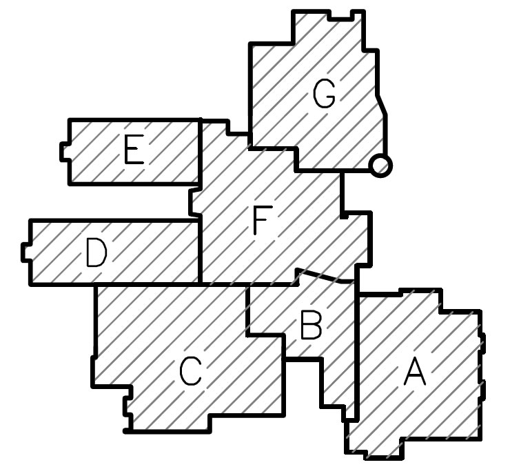
The high school for this project was broken down into seven different construction areas as shown. By breaking the building up into smaller pieces it makes the construction process much more manageable. It allows for the schedule to be broken down into more detail, and makes communication easier. The project schedule on this job is of extreme importance. Although the entire job is scheduled to be completed in 3 years, HESS only has 18 months to build the replacement school. Because of this tight time frame it is imperative that the CPM schedule is met. Notice to proceed for this job was given on the 1st of December 2011 and the school must be complete and turned over in August for the 2013 school year. Before any work could start on this project the site had to be cleared of existing features. This also included the partial demolition of the existing gymnasium. Once the site was cleared, fill had to be brought on site and compacted to provide adequate bearing for the schools foundation. This whole process took approximately 65 days, at which point the foundation work began. The placement of foundations, structural steel/load bearing masonry, and the building enclosure all follow a progression when put in place. The path of construction for this work went from Section F to E, to D, to G, to C, to B, to A. During this time there was overlap in activities occurring simultaneously. That is to say that when foundations in C were being placed, structural steel was being erected in area F. This staggering of activities greatly improves construction time. This can also be seen in the schedule for interiors; however there is much more overlap in different sections of the building. After all of the final inspections are complete and the school is turned over the demolition of the existing school begins. Once demolished, the site will be transformed into a new parking lot for faculty and students. It is during this time the remaining sports fields will be completed. |
||||||||||||||||||||||||||||||||||||||||||||||||||||||||||||||||||||||||||||||||||||||||||||
ELECTRICAL/LIGHTING |
||||||||||||||||||||||||||||||||||||||||||||||||||||||||||||||||||||||||||||||||||||||||||||
The main electrical room is located in the south west corner of the building and is fed from two separate 2,500 KVA pad mounted transformers supplied by PEPCO just outside the building. Each transformer ties into its own 3,000 amp 480/277 volt switchboard with ground fault protection. A backup generator is located in close proximity to the building to power emergency equipment in the event of a power outage. Additional panelboards and step down transformers are located throughout the building to supply power to all necessary equipment |
||||||||||||||||||||||||||||||||||||||||||||||||||||||||||||||||||||||||||||||||||||||||||||
MECHANICAL |
||||||||||||||||||||||||||||||||||||||||||||||||||||||||||||||||||||||||||||||||||||||||||||
The mechanical room for the high school is located on the first floor in the south west corner of the building. To ensure the building operates and performs as intended a Building Automation System (BAS) is used to observe and control the schools environment which is monitored both on and offsite. If communication with the system is ever lost the controller will revert to its inherent set points. The mechanical room has nine 30 ton water to water heat pump modules to manage the four geothermal fields and two geothermal vaults of 437 combined wells all at a depth of 400 feet. The 12” supply and return pipes for this system travel over 1,600 feet each, from building stub up to geothermal vault. The fields encompass approximately 207,000 square feet and sit underneath the proposed football and baseball fields. In addition to the nine modules the mechanical room also houses 10 pumps, four expansion tanks, two gas-fired hot water boilers, and a slew of other equipment. There are two Dedicated Outdoor Air Systems (DOAS) with a combined 28,170 CFM capacity that serve the north and south wings of the building. Each of these DOAS’s have a heat recovery wheel and are connected to three indoor air handling units (one on each floor of the classroom wings.) In addition to this there are 17 separate rooftop air handling units, nine of which have energy recovery wheels. To ensure a healthy indoor air quality all outdoor air intakes have an airflow monitoring system to measure contaminants in the air. Air flow is distributed throughout the building in sheet metal ducts and zone controlled by VAV boxes. |
||||||||||||||||||||||||||||||||||||||||||||||||||||||||||||||||||||||||||||||||||||||||||||
STRUCTURAL |
||||||||||||||||||||||||||||||||||||||||||||||||||||||||||||||||||||||||||||||||||||||||||||
The new high school is a combination of both CMU load bearing walls and structural steel. The columns for the building are hollow structural steel (HSS) members and wide flange beams supported by at least an 18” by 18” concrete pier on spread footings. Columns are spliced at the third floor level for areas D, E and F. All wide flange beams and girders conform to either ASTM A-572 or A-992 and are of grade 50 (50,000 KSI). Lateral structural steel support is accomplished through the use of cross bracing in 33 different locations and welded moment connections in four bays. The floors-on-deck of the building are constructed of 3-1/4” light weight concrete on 2” galvanized composite steel deck with welded-wire-fabric, and shear studs. Roofs are comprised of 20 gauge 1-1/2” type B roof deck on K-Series and LH joists. A 150 ton crawler crane was scheduled to place all structural steel for the building, but because of a loss of time in the schedule a second crane was brought on site to expedite construction. As was mentioned before, a large portion of this high school is constructed out of load bearing concrete masonry units (CMU’s). Building sections A, B, C, and G are comprised almost entirely out of load bearing CMU walls. These walls range greatly in thickness depending on their location in the building. In some cases they serve as both structure and architectural façade. Much of the masonry units are placed off of scaffolding. |
||||||||||||||||||||||||||||||||||||||||||||||||||||||||||||||||||||||||||||||||||||||||||||
FIRE PROTECTION |
||||||||||||||||||||||||||||||||||||||||||||||||||||||||||||||||||||||||||||||||||||||||||||
| Fire suppression for the school consists of an automatic sprinkler system with high temperature heads in conjunction with a heat and smoke detection system. In locations where duct penetrates fire rated walls fire-dampers are installed. The server room for the school (Rm. F-255) works on a pre-action fire protection system to make sure the system doesn’t accidentally go off. | ||||||||||||||||||||||||||||||||||||||||||||||||||||||||||||||||||||||||||||||||||||||||||||
TRANSPORTATION |
||||||||||||||||||||||||||||||||||||||||||||||||||||||||||||||||||||||||||||||||||||||||||||
| The school is equipped with 2 elevators shafts, but only one elevator. The reason only one elevator was installed was to decrease costs on the project. There are also four stair cases. Three of these stair cases are fire rated and serve as egress. The fourth stair case is a large spiral stair that connects all three levels. | ||||||||||||||||||||||||||||||||||||||||||||||||||||||||||||||||||||||||||||||||||||||||||||
TELECOMUNICATIONS/SECURITY |
||||||||||||||||||||||||||||||||||||||||||||||||||||||||||||||||||||||||||||||||||||||||||||
| The school has an extensive video surveillance system, intrusion detection system and several telecom rooms. | ||||||||||||||||||||||||||||||||||||||||||||||||||||||||||||||||||||||||||||||||||||||||||||
Note: While great efforts have been taken to provide accurate and complete information on the pages of CPEP, please be aware that the information contained herewith is considered a work‐inprogress for this thesis project. Modifications and changes related to the original building designs and construction methodologies for this senior thesis project are solely the interpretation of Christopher Ankeny. Changes and discrepancies in no way imply that the original design contained errors or was flawed. Differing assumptions, code references, requirements, and methodologies have been incorporated into this thesis project; therefore, investigation results may vary from the original design. |
||||||||||||||||||||||||||||||||||||||||||||||||||||||||||||||||||||||||||||||||||||||||||||
This page was last updated on January 12, 2012, by Brady Sheerin and is hosted by the AE Department © 2013 |
||||||||||||||||||||||||||||||||||||||||||||||||||||||||||||||||||||||||||||||||||||||||||||
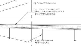 Roofing