Lowell Stine |
Construction Option |
2013-2014 |
|
Library In Metropolitan Washington D.C. |
Building Statistics |
|
|
|
| |
General Building Data |
Building Name |
Library In Metropolitan Washington D.C. |
Location |
Metropolitan Washington D.C. |
Occupant Name |
County Library and a Non-profit Art Group |
Function Types |
A-3 (Assembly) - Art gallery, library, meeting rooms, conference rooms, etc.
B (Business) - Staff office areas, art studios, coffee bar.
M (Mercantile) - Art store in fit out space. |
Gross Floor Area |
90,000 Square Feet |
Number of Stories |
One below grade and five above grade plus a mechanical penthouse |
Project Delivery Method |
Design - Bid - Build |
Dates of Construction |
January 2013 - October 2014 (630 Calendar Days) |
Cost Information |
This project is estimated to cost $69,530,000 which includes the purchase of the land. This cost also includes the required utility work, building construction ($35,000,000), furniture and equipment, security, telephone systems and computers, and new books and media. Also included in this cost estimate is the indirect costs associated with consultant fees and permitting fees. |
Project Team |
Owner: Undisclosed County
|
MBP
|
Civil Engineer: ADTEK
|
Architect: The Lukmire Partnership
|
Mechanical & Plumbing Engineer: Mendoza, Ribas, Farinas & Associates
|
Landscape Architect: Parker Rodriguez
|
Contractor: Costello Construction
|
Electrical Engineer: Mendoza, Ribas, Farinas & Associates
|
Interior Design: The Studio of Sandra Ragan
|
Structural Engineer: Columbia Engineering
|
IT/Security: Wright Engineering
|
Lighting Consultant: MCLA
|
|
|
| |
|
Architectural |
Architectural Overview |
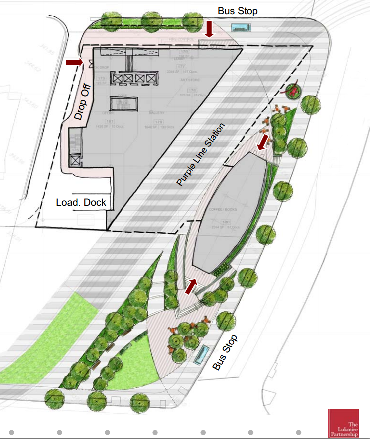
The Lukmire Partnership used a charrette design process on this project, which is a method of design where the general public was able to voice their feedback of the building's design. The result was a building that serves as a monument to the surrounding areas that can hold 1,827 occupants at full capacity. About two thirds of the 90,000 square feet building will be occupied by the library space, which will be located on the third, fourth, and fifth floors. The other one third will consist of a small coffee shop on the first floor and a space that is to be fitted out by a non-profit art organization, which will be occupying part of the first floor and the entire second floor. Much of the library space is open with plenty reading areas located along the exterior walls. On the first and second floor the fit out spaces are not currently design. |
Unique Architectural Elements |
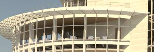
The most interesting architectural element of this building is how the architect incorporated the future light rail link stop into the building's form (As seen in picture to the right). The proposed location for the train stop calls for it to intersect the building. The architect incorporated this into the east, third floor entrance to the library by creating a glass, partially circular pavilion that is broken away from the first two floors to transport visitors directly to the library level. With a daring leap of faith the three story library then spans across this broken gap while also partially cantilevering the three floor glass north corner over the future train stop. When the basic shapes the architect used come together they create a monumental addition to this down town area |
|
|
Building Codes Applicable |
NFPA 101 - 2003 & 2009 |
IECC 2009 |
NFPA 72 - 2002 & 2007 |
NEC 2008 |
NFPA 13 - 2002 & 2007 |
WSSC 2011 |
IBC 2009 |
ALL COUNTY AMENDMENTS |
IMC 2009 |
2010 ADA STANDARDS FOR ACCESSIBLE DESIGN |
IFGC 2009 |
COMAR 05.02.02 |
|
Zoning |
The current zoning designation for this site is CBD-1 (Central Business District), but the zoning is proposed to be changed to CR-3.0 (Commercial Residential). This new zoning will be geared more towards mixed use buildings and pedestrian areas/movement with easy access to transit options, which could include metro, light rail, and bus transportation. |
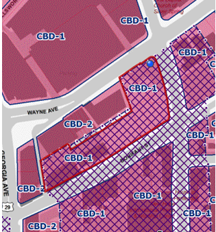
Picture Provided by County's Zoning Map
|
|
Historical Requirements |
There is no historical requirements for this project. |
|
| |
|
Building Enclosure |
Building Facades |
There are a three types of building enclosure systems that are in play in this project. The first and most recognizable being the glass curtain wall system that encloses approximately 50% of the building. Aluminum frames and UV protective glazing make up the curtain wall that encloses most of the third through fifth floors and the pavilion.
Another enclosure system is the terra cotta panels that are to be white and either flat or grooved. NeaCera Terra-cotta Rainscreen Panels will be used that are designed using Lift and Lock Technology, also including Graffiti Protection. In this system the panels are reinforced which ties into the hanging mechanisms. Behind these panels will be ridged insulation and in most cases 8'' or 6'' cold formed metal studs. Prefinished architectural concrete masonry units are also used in some locations on the first two levels as well as the elevator tower in the pavilion. |
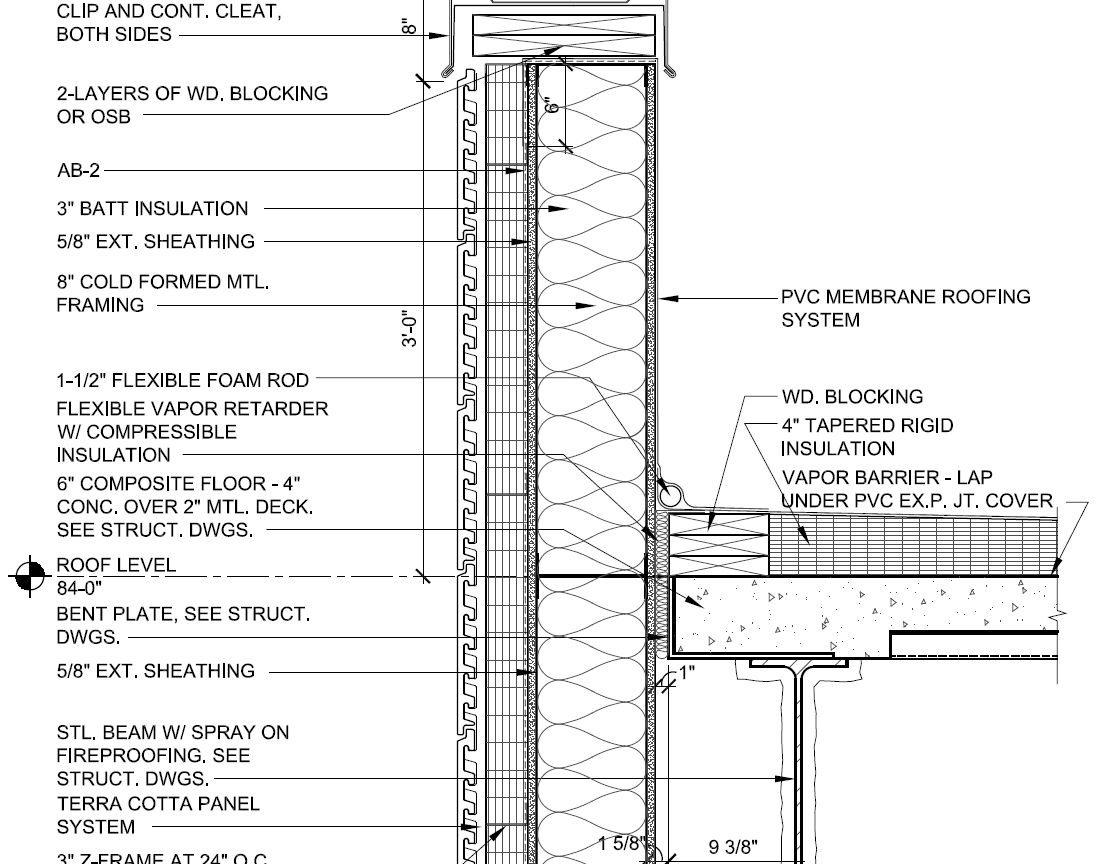
Both Provided by Construction Documents From MBP |
|
Roofing Types |
Much of the building's roofing is a green roof system with pavers on adjustable height pedestals that make walk ways on the roof. The green roof is built up from a 4'' concrete roof deck, rigid insulation, a vapor barrier, a thin layer of fine stone, and an 8'' thick engineered soil layer. |
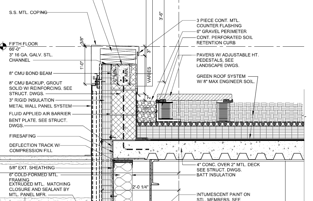
Both Provided by Construction Documents From MBP |
|
|
| |
|
|
Construction |
As mentioned before construction will begin with the Notice to Proceed on January 7, 2013 with substantial completion on September 30, 2014. Move-in will be continuous for about a month with the final opening day on October 30, 2014. Design-Bid-Built project delivery was used on this project, in that the design was 100% complete when the bid documents were released to the qualified contractors. Lump sum contracts are held between the County and the architect and contractor. Time & Material contracts are held between the County and the construction manager and quality control consultants.
Means & Methods
All cast-in-place concrete walls and shear walls on the project are formed using a wall form that interlocks with itself to require minimal amount of bracing. Concrete on site will be poured using a shoot, crane and bucket, and concrete pump, depending on the circumstances. A 200 ton crawler crane will be used to erect the structural steel for the project. Sequencing of the structural steel and elevated composite decks will start at floor one progressing to floor two. On floors three through five the superstructure will be erected in the pavilion and in the wedge portion of the building. Once the roof trusses have been set, then the remaining steel and concrete slabs can be placed and rough-in in those floors can begin.
Constructibility Concerns
Caisson bearing capcity is important on this project because the first few feet of soil on the site is not capable of supporting any amount of substantial loads. This is why caissons are used to extend down past this unsuitable soil to a soil that is capable of supporting the building's loads. In all the caissons the structural designer specified planned depth based on the geotechnical report and test boring logs. With these depths, prefabricated rebar cages where manufactured and shipped to the site. However, the actual depths to reach proper bearing capacity differed than the planned amount, which meant the rebar cages were not the proper size. Each rebar cage had to be altered individually to match the new altered caisson lengths. This has created delays and cost over runs in the project that are still being made up for today.
As mentioned before, roof trusses will be supporting the overhanging section of the building. Two of these roof trusses are 110' in length. This is far to long to be transported to site in one load. Instead the trusses will be spliced, one section being 60' and the other being 50'. These three splices per roof truss are critical to the building stability because they will be under an extreme amount of moment when fully loaded with the three floors of the library. To ensure the highest quality welding for these splices, the welds will be done on the ground before setting the trusses, and the welds will be inspected using ultrasound technology. Once the welds are approved and signed off on, the truss can then be set as one lift.
A unique feature of the HVAC system in this building is that it uses an integrated packaged equipment center (IPEC), which is a prefabricated mechanical penthouse that houses most of the building's mechanical equipment (for a more detailed description, please see the Mechanical System description below). This unit has created a great deal of controversy between the project team because the original specified manufacturer no longer makes the required unit. A different manufacturer was chosen through a change order, and now this manufacturer has been uncooperative in providing information to the project team that is required for coordination issues. Trades that must be coordinated in conjunction with the IPEC is at minimum the structural steel, membrane and green roofing, electrician, plumbing, fire protection, and sheet metal duct installers. These are most of the trades that must tie into the IPEC unit in someway while its being placed or after it is placed. The coordination process for the IPEC is an on going project that is currently still being planned and worked out. |
|
| |
|
Electrical System |
Pepco is the electrical utility company in this geographical location. Two underground electrical utility feeders enter the building through the northern side and are metered separately. One meter is for the coffee shop on the first floor and feeds a 277/480V 400A transocket. The coffee shop service is then fed into a single main distribution panel supplying power to two 100A panel boards, which are stepped down to 120/208Vand a 70A feed to the IPEC.
The other meter is supplying power to a 277/480V 3000A switch board with three distribution sockets and a generator socket. A 250KW natural gas fired generator is located on the roof of the library with a 100A and a 400A automatic transfer switch. One of the sockets in the switch board is a 800A feed to the IPEC. Because the IPEC is per-manurfactured, the only electric work required for its operation is this 800A feeder. Of the other two sockets in the switch gear one is for a 100A panel board that feeds the first two floors that will be fitted out in the future. On the other hand, the other socket feeds a 600A main distribution panel for the rest of the building. There is a main panel board on each floor that distributes power to smaller panel boards for final distribution of receptacle and lighting loads on that floor.
The primary electrical loads in this building are lighting, office/ computer, receptacle , and the IPEC (pumps and fans). All site lighting is powered directly from Pepco and is not metered through the library. |
|
| |
|
Lighting System |
All lighting controls for the library and pavilion spaces are from one central light management hub. This hub system has an energy saving node on each floor that sends and receives information from the hub. This system can be completely controlled remotely through any Internet connection using Lutron's interactive facility maintenance interface. Each floor acts as a primary zone and then can be broken up into multiple sub-zones from each of the nodes. In each designated zone information is gather about occupancy, time of day, and amount of day light. From this gathered information the hub can automatically control the lighting in each zone by turn on, off, or dimming the lights. This is achievable because each light fixture is powered using Ecosystem full dimmable ballasts. The hub also has an emergency lighting interface in which only essential lighting can be controlled during an emergency.
Florescent and very few LED interior lighting fixtures and high pressure sodium exterior lighting fixtures are used on this project. |
|
| |
|
Mechanical System |
The IPEC unit has the most mechanical equipment located in it. Internally in the IPEC is the building's pumps, air handling units, natural gas fired boilers, chillers, heat recovery system, cooling towers, and outside/ exhaust air louvers. There is one air handling unit that is 40,000 CFM and one that is 16,000 CFM and three 800 MBH boilers. On floors one and two there are small mechanical room that only house heat pumps large enough to condition those lower spaces.
Forced air is conditioned and supplied at a rate to satisfy ventilation and most load needs. Remaining heating and reheating are performed using hot piping. This pipping and all supply and return ducts are installed in the mechanical shaft located on the west side of the building. Variable air volume terminals with hot water coils and conditioned are supplies are used to condition each space to the exact desired temperature. This systems allows there to be many different zones with very precise control over all of them individually, while supply enough air for ventilation. A unique item in the mechanical system is the in-slab hydronic heating that is used in a few areas where overhangs may have issues with cold floors. |
|
| |
|
Structural System |
Much of the substructure of this building is made up of cast-in-place concrete. 5000 psi concrete caissons are used as the means of deep foundations, which are 30'' to 72'' in diameter that must be penetrating at least 5' of suitable bearing capacity soil, and the caissons are reinforced with steel rebar cages. (16) of the 46 caissons are supporting three separate 42'' to 54'' thick 5000psi mat foundations that act as bases for the three 5000 psi concrete shear walls (1' thick). Around the perimeter of the building is a 1' thick perimeter foundation wall that bears partially on the rest of the caissons.
Structural steel, elevated floor slabs, and two concrete columns makeup the superstructure of this building. The structural steel frame has beams ranging from W10x15 to W40x215 and columns that all have a W14 member size. All structural steel framing in the pavilion area is a variety of hollow structural section sizes that the curtain wall will frame into. The elevated floor slabs are composite in type, in that they are made up of 6x6 welded wire fabric, 2'' composite floor decking, a 4''-5'' 3000 psi concrete floor slab, and shear studs spaced 1' apart (on average) along each structural beam. An interesting and most unique portion of this building lies in the structure that is the result of the architectural elements of the building. A 50' cantilever is designed to span over the northern most portion of the train platform. To support the weight of three stories of library that will be bearing on this cantilever, (2) 15' tall and 110' long roof trusses will be installed, as two sections, on top of the two northern most column lines (as metioned above). To support the floors that are over the cantilever, structural members are then hung from the trusses and put in tension. Also, because of this cantilever, the western most column supporting each of these two trusses will be put in tension, which requires extra consideration in designing the foundations for these columns as well as concrete encasement in the basement level. All roof trusses on this project are W14x99 to W14x283. |
|
| |
|
Fire Protection System |
There is an extensive smoke exhaust system and smoke detection system in the supply and return duct mains in case of a fire. The entire building is sprinkled with wet action sprinklers in most areas. However, there are sprinklers over the train platform that are per-action to prevent the water in the lines from freezing. Also, the underside of the third floor that is exposed above the train platform has an add alternative to improve the fire rating of this area in the event a train were too catch on fire while stopped at this stop. |
|
| |
|
Transportation System |
Because this building will primarily be open to the public, how people flow in/ out and up/ down through the building is important. There will the two elevators in the pavilion area, two at the northern lobby, and one by the southern loading docks for staff only. Only the south elevator goes from the basement to the roof, while the pavilion elevator runs from the first floor to the fifth floor with no stop on the second floor and the north elevator runs from the basement to the fifth floor. Also in the pavilion is a set of escalators that brings people from the first floor directly to the third floor library entrance and a stairway that also serves this same purpose. There is also a set of stairs that are internally positioned in the library that go from floor three to floor five. Special consideration was taken when designing these vertical transportation means because of book theft concerns. To address these concerns some of the elevators are equipped with card access to certain floors going down, but with access to all floors going up, which is to prevent someone from walking out of the building with books that are not checked out. |
|
| |
|
Telecommunications System |
Telecommunication lines enter the building through (8) 4'' conduits in a concrete duck bank from the telephone company manhole on the west corner of the site and run in racks to the building's data center room. This room houses the fiber rack, data rack, security rack, radio equipment rack, and the Verizon Interconnections. Each floor in the library has an IT room in which houses servers and acts as a central telecommunication riser for the distribution and maintenance of the building's IT and security network. There are a variate of phone and Ethernet jacks located throughout the library in offices, meeting rooms, and computer areas. |
|
| |
|
Special Systems |
A new radio frequency inventory device (RFID) is budgeted into the construction cost of the library. This new system is am improvement from the system that is currently in use, which will only allow a single person to borrow 50 books before they are required to return some in order to check more out. This limitation will not exist on the new system. Also, the new RFID system will sort the books being dropped off at the "Book Drop-off" and place them into appropriate bins organized by category. To prevent books from getting damaged from miscellaneous object that get put into the book drop-off, the RFID will recognize that the object is not a book and will place it in a special bin to be disregarded by a librarian. |
|
| |
|
| |
User Note: While great efforts have been taken to provide accurate and complete information on the
pages of CPEP, please be aware that the information contained herewith is considered a work in in progress
for this thesis project. Modifications and changes related to the original building designs and
construction methodologies for this senior thesis project are solely the interpretation of Lowell Stine. Changes and discrepancies in no way imply that the original design contained errors or was
flawed. Differing assumptions, code references, requirements, and methodologies have been
incorporated into this thesis project; therefore, investigation results may vary from the original
design. |
|
|
This page was last updated on 10/19/2013, by Lowell Stine and is hosted by the AE Department
©2013
|
|
| |
.jpg)
.jpg)