- Bridgeside Point II (also known as Bridgeside Building II)
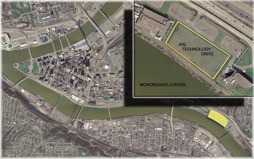
- 450 Technology Drive (Pittsburgh Technology Center) along the northern bank of the Monongahela River near the intersection of 2nd Ave and Bates St.
- Potentially a University, TBD
- Laboratory and office space
- Approximately 150,000 square feet
- 5 stories and 74'-6" to top of steel on roof
- November 2007 -- TBD
- Approximately $18 million (GMP)
- Design-Bid-Build
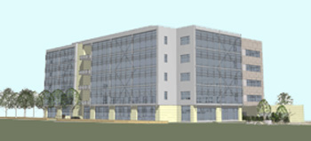
Bridgeside Point II is a 5-story building with a combination of office and laboratory space to be built with the 48-acre Pittsburgh Technology Center just east of downtown Pittsburgh.
The Pittsburgh Technology Center is quickly becoming a beacon of modernization and technological advancement as seen through the work done by The University of Pittsburgh, Carnegie Mellon, and Cellomics in the areas of Biotechnology and Bioengineering. Once the site of a steel mill, the site has been transforming into sleek, streamline buildings with expansive green-spaces symbolizing the shift of heavy industrialism to revolutionary research and development.
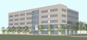
Bridgeside Point II clearly emphasizes this progressive feel through its clean lines, visible lateral bracing, and open plan. Precast stone panels wrap the ground floor while the upper floors are complimented by profiled metal panels. The design team continued with the theme of forward thinking by creating an open plan, flexible building systems, and roughly 15'-0" floor to floor heights allowing ultimate customization by the tenant.
-
- 2006 International Building Code
- 2006 International Energy Conservation Code
- 2006 International Fire Code
- 2006 International Fuel Gas Code
- 2006 International Mechanical Code
- 2006 International Performance Code for Buildings and Facilities
- 2006 International Property Maintenance Code
- 2005 National Electric Code
Bridgeside Point II is situated approximately 2 miles east of Pittsburgh proper along the northern banks of the Monongahela River in the recently created Pittsburgh Technology Center. The site was once home to the Jones & Laughlin Hot Strip Mill, but was purchased by the Urban Redevelopment Authority of Pittsburgh in 1983.
The previous zoning of this site was GI (General Industry), but was changed in the spring of 2006 to SP-1 (Specifically Planned District #1) specifically for the continued development of the Pittsburgh Technology Center.
Bridgeside Point II's building envelope was designed to emphasize advancement in technology. This is done through the use of a glass curtain wall, which engulfs almost the entire facade, large metal panels, and precast stone panels. As the eye travels vertically along the building, a sense of progression is made as stone gives way to the glass and metal, which essentially gives the building a feeling of transparency and weightlessness.
Light gauge metal studs are used in conjuction with the precast stone and metal panels. The glass curtain wall utilizes aluminum framework, and with such large glass openings the lateral system actually becomes part of the visible architecture of the building.
The roof envelope is encompassed by a parapet wall. Two roof systems are used: one is a 1-1/2" metal deck and the second is a 6" composite deck (3" concrete depth). Both systems are topped with a rubber membrane, rigid insulation, protection board, and flashing at the parapet walls and at penthouse supports.
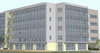
Corner View Showing Lateral Bracing and Glass Curtain Wall
Bridgeside Point II's typical floor system is composite steel framing with normal weight concrete and a total floor thickness of 6". Composite action is created by 3"-20 gage composite steel deck with 5-1/2" long, 3/4" diameter shear studs. In a typical bay, W21x44 beams span 32'-0" and are spaced approximately 10'-0" center to center. These beams frame into W24x62 girders with a shear connection. Column sizes vary depending on their location within the building, but are typically W10 to W14.
The lateral load resisting system of Bridgeside Point II takes advantage of several large braced frames. These frames are located around the perimeter of the building in order to decrease the impact of the braces on the open plan. The frames are comprised of HSS8x8x3/4 up to HSS10x10x1/2 diagonals and heavy W14 columns.
The roof system is composed primarily of K-series joists; however, wide flange shapes are used in densely loaded areas such as areas with rooftop air handling units and the boiler room. Areas with joists support a 1-1/2", 20 gage galvanized steel roof deck with 3" of concrete. Areas with wide flange shapes utilize the same composite deck system found throughout the rest of the building.
Bridgeside Point II's main foundation system is a driven pile sytem with nearly 170 piles. The more typical 3'-6" thick reinforced concrete pile caps consist of 2 or 3 HP10x57 piles designed for end-bearing. In high load cases, 4'-6" thick reinforced concrete pile caps consisting of 7 to 9 HP14x73 piles designed for end-bearing and 30 kips uplift. Between all exterior pile caps is a 3'-0" deep grade beam which transfers any facade and wall load to the foundation system. The elevator pit is supported by a 3'-6" thick reinforced concrete pile cap with 6 piles. The reinforced concrete pit walls are 12" thick and 5'-6" high. The ground (main floor) rests on a 4" concrete slab reinforced with W/6x6-W1.4x1.4 welded wire fabric.
Not available at this time. Construction date will be determined in November. Information will be added as it is received.
Bridgeside Point II's mechanical system is designed for both office and laboratory space. For any laboratory spaces a dedicated rooftop unit supplies 100% outdoor air capable of 40,000 CFM. This unit is equipped with a high efficiency filter to ensure ideal indoor air for laboratory spaces. There are two office space rooftop units at the site. They both employ heat recovery wheels that operate in the mid-70% range for efficiency, and they can supply up to 75,000 CFM (17,000 CFM coming from outdoor air).
Every floor of the building is equipped with VAV (Variable Air Volume) and PFP (Parallel Fan Powered) boxes for optimal heating and cooling. The VAV boxes provide roughly 1150 CFM, while the PFP boxes provide up to 2100 CFM. The floor plan is separated into main zones and then further divided into subzones based on occupancy and thermal loads. Each floor has a minimum of four exhaust ducts for increased flexibility in space layout.
The building has a main boiler area on the roof which houses 7 - 532 GPM boilers as well as two primary and two secondary capable of up to 226 GPM. Domestic water is provided to each floor through 6" mains, which is then distributed to the appropriate holding tanks per floor. This system is capable of recovering a 15,000,000 BTU heat loss.
Incoming power to Bridgeside Point II is provided by Duquense Light at 480Y/277V. This system is a 3 phase, 4 wire system that reduces down to 208/120V for receptacle and lighting loads through 30kVA transformers located on each floor except for the third. Every floor has automatic transfer switches for emergency power which is provided by a 1 megawatt emergency generator.
The building is card access ready and surveillance camera ready.
The electrical system will be completed by the tenants to suit their needs upon their occupation of the building.
Lighting on the typical floors will be installed by the tenant. Core spaces like the lobby, restrooms, and corridors have a mix of lighting. Restrooms and corridors have 8" diameter recessed fixtures with compact fluorescent bulbs, while the lobby is furnished with several different lighting fixtures. Typically recessed lighting is used; however, reception spaces are accented by pendant light fixtures. Each floor is equipped with emergency lighting.
Bridgeside Point II is equipped with automatic sprinkers and is fully sprinkled. The loading dock and the area under the canopy are protected by a dry pipe system, while interior spaces utilize a wet system in the event of an emergency. In addition to sprinklers, all spaces implement fire alarms.
Most of the building's wall systems are rated for 2-hour fire protection. The structural steel framing is rated per IBC 2006.
Bridgeside Point II's main entrance is located off of Technology Drive. The main entrance consists of a lobby space and a single core elevator. From the lobby, there is access to 3 gearless traction elevators with a 3,500 pound capacity per elevator. The building also has two stairwells located approximately at the building's third-points along its north/south direction which serve every floor with card access.
The building occupant will provide the communication systems as necessary; however, every floor is pre-equipped with the required communication jacks for easy installation.
No special conditions or elements are in place at this time.
|