Arlington, VA
| |
| Home |
| About Megan Kohut |
| Building Statistics |
| Thesis Abstract |
| Technical Reports |
| Thesis Research |
| Thesis Proposal |
| Thesis Presentation |
| Final Report |
| Reflection |
| Senior Thesis e-Studio |
Note: While great efforts have been taken to provide accurate and complete information on the pages of CPEP, please be aware that the information contained herewith is considered a work-in-progress for this thesis project. Modifications and changes related to the original building designs and construction methodologies for this senior thesis project are solely the interpretation of Megan Kohut. Changes and discrepancies in no way imply that the original design contained errors or was flawed. Differing assumptions, code references, requirements, and methodologies have been incorporated into this thesis project; therefore, investigation results may vary from the original design. |
![]()
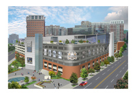
Building Statistics
General Building Data
- Building Name: Kettler Capitals Iceplex
- Building Location: 627 N. Glebe Road, Arlington, Virginia
- Building Occupants: Washington Capitals, National Hockey League, and the general public
- Building Function: Mixed use (parking structure, offices, retail, sporting venue)
- Size: 137,000 SF (not including parking structure)
- Height: 9 floors, 103 ft.
- Dates of Construction: January 2005 – present
- Project Cost: $42.7M (total project cost)
- Project Delivery Method: Design-Bid-Build
Project Team
- Owner/Developer: Lincoln Holdings, Arlington County / Jones Lang Lasalle
- Architect: Architecture, Inc.
- Civil Engineer: VIKA
- Structural Engineer: Rathgeber/Goss Associates
- MEP Engineer/Fire Protection Engineer: K.T.A. Group
- Construction Manager: Sigal Construction Corporation
- Food Service Consultant: Tricon Foodservice Consultants, Inc.
Architecture
- Description
The Kettler Capitals Iceplex is located on top of a parking structure at the Ballston Common Mall at the intersection of Glebe Road and Randolph Street in Arlington, Virginia. The Iceplex is connected to the mall through the parking structure and is directly linked to the Metro Orange Line.
The new rink building was constructed over the original 1951 parking garage. This garage was designed as five levels of cast-in-place concrete reinforced with mild steel with the additional capacity for two levels of vertical expansion. In the 1980s, two levels of additional parking were added. Finally in 2000, design for the eighth floor ice rinks and ninth floor corporate/training facility began. At 60 ft above grade, the Kettler Iceplex is proud to be the home of the highest rink above street level in the US.
The complex was designed to a LEED Certified level but never registered with the US Green Building Council (USGBC) in order to pursue the rating. Using a variety of recycled materials and having natural light penetrate into 90% of interior spaces are two features that make Kettler a green building.
- Applicable Codes and Standards BOCA 1996
- Virginia Uniform Statewide Building Code 1999
- ANSI/ASCE 7-95
- 1996 National Electric Code
- ASHRAE/IES Standard 90.1-1989
- Zoning
The location of the Iceplex was rezoned during the design process in order to allow for the development. Now, the Iceplex is zoned as C-O-2.5 (Commercial Office Building, Hotel, Apartments).
- Historical Requirements
There were no requirements for this project.
- Building Envelope
The façade of the parking structure consists of reinforced concrete and brick. Like typical parking garages, many openings in the façade are needed to ventilate the area from car exhaust. This means that the building envelope of this part of the building does not give any protection from the elements.
The building envelope of the rink and office space is made of metal paneling and glass curtain walls. The curtain wall is supported using metal studs and kickers. The wall uses 1” insulated glazing in order to obtain a sufficient thermal barrier.
The roof membrane consists of a concrete slab on metal deck using a fully adhered EPDM roof membrane. Long-span trusses were required to support the roof above the ice rinks.
Structural System
Since the Kettler Capitals Iceplex was constructed on top of an existing parking structure, there were many challenges for the structural design of the building. Design for the Iceplex began in 2000; however, this was the third time the Ballston parking garage has been expanded. The original facility, which dates back to the 1950s, was a five story cast-in-place concrete structure reinforced with mild steel. Then in the 1980s, the parking garage was expanded two more times. In 1981, a five story L-shaped addition was constructed of cast-in-place posttentioned concrete. Then in 1986, the existing five level structure was topped with two more levels, one posttentioned concrete and the other composite steel.
The actual load of the new Iceplex was about three and a half times that of the allowable expansion load. Consequently, reinforcing the existing structure was required. After testing the soils, it was determined that two footings needed to be expanded 3 ft. in one direction. The existing columns were analyzed for the additional load of the new structure. A total of 11 columns were wrapped in carbon fiber reinforcing. Also, all existing steel columns on levels 5 and 6 of the parking garage were encased in concrete.
Two expansion joints were used in the construction of the new Iceplex. One running in the north-south direction separates the 8th level of parking from the 8th level of the Iceplex which is where the ice rinks are located. The other expansion joint, running east-west, separates the ice rinks from the Capitals corporate offices and training facility.
It was important to limit deflection of the concrete slab supporting the rinks in order to prevent the ice from cracking. The structural engineer and the ice rink consultant compromised to limit the deflection to L/480. This slab was constructed from 3½” lightweight concrete over 3” 18 gage galvanized composite deck (total thickness = 6½”) reinforced with #4 at 16”oc each way 2” below the slab. Supporting the slab are mostly composite W18x40s at 9’-0”oc spanning 30’-0”. These W18s frame into larger steel composite beams which range from W21x50s to W36x150s. All shear studs are ¾” dia. x 4” long. Steel columns supporting the rinks range from W12x58s to W14x257s.
The need for long-span, column free spaces was critical in the design of the roof over the two ice rinks. The roof joists above the rinks are open web steel joists, 68DLH16. These joists have a depth of 68” and have the capacity to support large loads with extremely long spans. The span of these roof joists are 120 ft. and are spaced at 5’-6”oc.
There is a mix of lateral resisting systems throughout the structure. The original parking structure that was built in the 1950s was constructed using a two-way slab system. During the 1980s expansions, moment frames were designed to resist lateral loads. Finally, during the construction of the new Iceplex, a mix of braced frames and moment connections were used.
Mechanical System
The mechanical system serving the main ice rinks consists of a desiccant based dehumidification system combined with a refrigerant based cooling system all packaged in three separate roof mounted units. The purpose of these systems is to keep the air space that contacts the ice between 10 to 20 degrees F above the ice surface temperature. Since the ice surface does evaporate and contribute water vapor to the airspace, these units are also responsible for removing this moisture from the air.
A network of refrigerant piping running under the entire ice surface creates the ice surface and maintains its temperature. The refrigerant used for this system is ammonia, which is cooled by industrial type chillers. The chiller room is located next to the ice melt pit in between the two ice rinks.
The locker rooms, bathrooms, and many of the utility rooms use various exhaust systems. The party rooms, faculty offices, locker rooms, and other remaining spaces are ventilated and air conditioned by four refrigerant based packaged constant volume rooftop units with extensive ductwork and air distribution systems.
The team offices, team locker rooms, coaches' rooms, and team training facilities are all ventilated and air conditioned by four refrigerant based packaged variable-air-volume (VAV) rooftop units. These units work in conjunction with VAV zone terminal units (VAV boxes) that vary the amount of cooling or heating into the zone they serve by varying the amount of air provided to these spaces. These VAV boxes act as a damper/valve and also include electric reheat. The VAV boxes operate based on a zone thermostat and the VAV rooftop unit is responsible for maintaining a constant supply air temperature and adequate airflow to the VAV boxes based on the demand.
Lighting/Electrical System
Electrical service consists of a 4000-ampere, 277/480 volt 3-phase, 4-wire, switchboard in the garage at level one. Service is extended to the Kettler Capitals Iceplex, at the new eighth level, through a distribution switchboard by bus ducts. Distribution throughout the facility is at 277/480 volts to several electric rooms located throughout the facility. If transformation is required to 120/208 volts, step-down transformers are provided at the electric rooms. The vast majority of lighting equipment is served at 277 volts. The majority of mechanical equipment is served at 277/480 volts. All other equipment that is not served at 277/480 volts is served at 120/208 volts. All branch circuit wiring is installed in conduit and Type AC cable was permitted when concealed. The facility has emergency power to support life safety systems and a fire pump. The majority of the lighting was required to be the same color temperature, 3500K. Although several manufacturers were used, most lighting fixtures were manufactured by Lithonia. Mounting types varied, but recessed and surface mounting were most widely used.
Construction Management
Sigal Construction Corporation was the project manager for the Iceplex. They acted as under a design-bid-build delivery method. The staging area for the new 8th and 9th levels was located on the 7th level of the existing parking garage.
Since the existing structure needed to be reinforced before constructing the new Iceplex, the architect prescribed a 6-phase plan starting in February 2005 and ending in June 2006.
- Phase 1: Expand footings
- Phase 2: Column Bolstering
- Phase 3: Underground utility work
- Phase 4: Crane installed on level 7 to erect steel for ice rinks
- Phase 5: Complete structural work for new stairs/elevators
- Phase 6: Complete construction within levels 8 and 9
Fire Protection System
The fire protection system is a standard wet system complying with NFPA sections 13, 14 and 24 and meets the requirements for high rise building structures. Based on the high rise requirements, and those of Arlington County, Virginia, 100psi must be maintained at the top of the standpipes. Thus a fire pump was required and is located at the ground level of the structure. Water was distributed to the standpipes using a fully charged wet system in unconditioned space and is protected from freezing by means of heat trace and insulation. The fire pump and heat trace are fed from an emergency generator. The heat trace system is fully alarmed to notify building engineers of failure in any portion of the system.