Baltimore Washington Medical Center Women's Center and Inpatient Tower
|
|||||||||||||||||
|
|||||||||||||||||
Megan Wortman Construction Management |
|||||||||||||||||
|
Building Statistics
General Building Data Building Name: Women’s Center and Inpatient Tower
Location and Site: 301 Hospital Drive, Glen Burnie, MD 21061
Building Occupant: Baltimore Washington Medical Center
Occupancy: Women’s Center Patient Care
Size: 310,290 SF
Number of Stories: Above Grade: 9 Total Levels 10
Primary Project Team: Owner: University of Maryland Medical System Construction Manager: Whiting-Turner Contracting http://www.whiting-turner.com/ Architect: Cannon Design / CCG Facilities Integration http://cannondesign.com / http://www.ccgfacilities.com/capabilities.html Structural Engineer: Whitney, Bailey, Cox & Magnani Mechanical / Plumbing Engineer: Leach Wallace Associates, Inc. Civil Engineer: McCrone, Inc Geotechnical Engineer: Marshall Engineering Scheduler: FTI Consulting http://www.fticonsulting.com/web/ Municipality: Anne Arundel County Maryland
Dates of Construction: Start-Finish: July 2006- March 2009
Cost: Building Cost: $59,386,202 Overall Project Cost: $68,173,861
Project Delivery Method: CM @ Risk
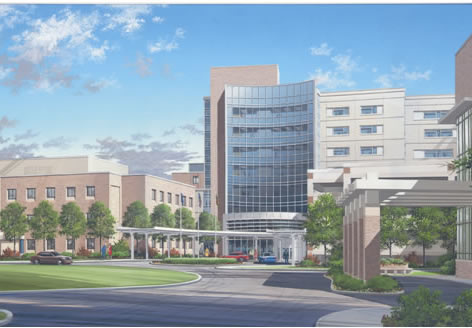
Architecture Architecture Description: Located at 301 Hospital Drive, the Women’s Center and Inpatient Tower is one of two new additions being built at the Baltimore Washington Medical Center in Glen Burnie, Maryland. The Baltimore Washington Medical Center, which is part of the University of Maryland Medical System, provides medical services for communities located between the Baltimore and Annapolis regions. With the addition of the Women’s Center and Inpatient Tower, the Baltimore Washington Medical Center will become an extensive care center for all patients throughout the state of Maryland.
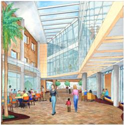
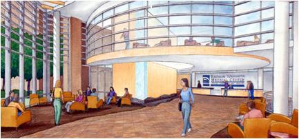
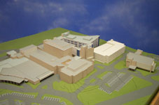
The new Patient Tower, which sits on top of what was an existing parking lot, is located adjacent to the existing six-story hospital and directly behind the main parking garage. Connected to the Patient Tower is the West Lobby Area, which is considered to be the front entrance of the tower. The West Lobby has a curved glass façade, and it is the only section of the tower that is completely visible from the entrance of the Medical Center. The West Lobby provides access to all levels of the new Patient Tower and also to the existing hospital. A bridge, which spans from the lobby area to the hospital and extends from level three through six, allows patients and guests to access the existing building using the West Lobby Entrance. Also located between the lobby area and hospital, is a small atrium. The atrium has three angled skylights, which allows plenty of natural light to enter the space. The Patient Tower itself is also connected to the existing hospital by a bridge. The bridge is located at the south edge of the building. This connector bridge joins the new patient rooms to the existing patient rooms for levels two through six.
The Patient Tower consists of a lower level, levels one through eight, and a roof penthouse. The lower level houses some mechanical equipment and most of the electrical equipment such as the generators and switch gear. Levels one through six consist of patient rooms, exam rooms, diagnostic testing rooms, c-section and labor rooms, infusion rooms, and sleep rooms. There are also nurse stations, waiting rooms, work areas, staff locker room and lounge areas, offices, and control stations located throughout these floors. Levels seven and eight are considered to be core and shell floors that are planned for future fit-out. The roof penthouse contains most of the mechanical equipment including two air handling units, two cooling towers, and one chiller.
National Building Codes: American National Standards Institute Anne Arundel County Plumbing Code 1993 Building Industry Consulting Services International International Building Code 2003 International Energy Conservation Code 2003 International Fire Code International Fuel Gas Code 2003 International Mechanical Code 2003 International Plumbing Code 2003 International Property Maintenance Code 2003 National Electric Code 2002 National Electrical Manufacturers Association National Fire Protection Association
Zoning: C2-Commercial Office District
Historical Requirements: Not Applicable
Building Envelope: The building envelope was designed to match the color and style of Baltimore Washington Medical Center’s Tate Cancer Center. This style consists of a variety of façade materials including glass curtain wall and windows, tan brick veneer, and EIFS panels. Most of the north, east, and west building façades are made up of the EIFS system with ribbon window units. On the north and west facades, tan brick veneer with ribbon window units extends from the lower level to level two. A glass curtain wall system is used for the West Lobby along with Stair Tower #2, which is located on the northwest corner of the Patient Tower. The façade for Stair Tower #1, which is located at the West Lobby Area, is tan brick veneer. Stair Tower #3, which is located at the southwest corner of the tower, is also tan brick veneer. The Roof Penthouse is composed of a composite metal panel system. The roof system for the Penthouse level is composed of an adhered EPDM sheet roofing with tapered rigid insulation on cast-in-place concrete. The main roof system is consists of an adhered EPDM sheet roofing with tapered rigid insulation on metal decking and structural metal framing.
EIFS System: EIFS (Exterior Insulation Finish System) panels on R11 Batt Insulation and 3 5/8” Metal Stud
Brick Veneer System: Tan Face Brick with 3” Rigid Insulation on either a CIP Concrete Wall or an 8” CMU Block Wall.
Glass Curtain Wall: ¼” Spandrel Glass and 1” Low E Tinted Insulated Glass
Ribbon Window Units: Aluminum Window: ¼” Spandrel Glass and 1” Low E Tinted Insulated Glass Accented Metal Panels
Composite Metal Panels: Aluminum Faced Composite Panels with R19 Batt Insulation on an 8” stud.
Primary Engineering Systems Construction: Whiting-Turner is the Construction Manager at Risk for the patient tower project. They hold a GMP contract with the owner. Whiting-Turner was awarded the contract for the construction phase of this project. Although most of the work is being performed by subcontractors, Whiting-Turner is self-performing the steel framing and precast concrete planks for the project. The site where the new patient tower is being constructed is a very congested site due to the existing structures that surround the construction site. The new tower is located at the west end of the Baltimore Washington Medical Center’s site. The site for the new tower is surrounded by the existing BWMC hospital and main parking garage and an apartment complex. Because the new tower is being built on a busy site where there are many people moving around the area, it is very important to monitor all activities on the construction site. To monitor the area, there are four job trailers located around the site. Most of the project team along with the owner’s representative is located in the three of the job trailers set up behind the existing hospital. These trailers were placed in this area to supervise who enters the site and also to check in any new subcontractors entering the site. The fourth trailer is located at the north end of the construction site in order to monitor all material deliveries being made to site. The construction began in July 2006 with the drilling of helical piers below the existing structure and the start of the foundation system. The construction process for the structure started at the south end and moved towards the north end. The concrete structure was poured by floors with 4 phases per floor. The concrete was placed using two concrete pumps. As the concrete structure was going up, the steel and precast planks were also being erected above the existing mechanical room. Two cranes were used to erect the steel framing and precast panels. Most of the steel was erected using the 150 ton hydraulic truck crane, which is located at the front of the west lobby area. The remaining steel along with the precast planks were erected using the flat top tower crane with a boom length of 246 feet and a capacity of 17,460 lbs, which is located on the west edge of the patient tower. Two material hoists were also used to transport materials. The two material hoists, which are located at the north end of the building, run from the lower level to level six. Because the elevators have not been installed yet, these hoists are critical in the transportation of materials to each level.
Structural System: The primary structural system for the new tower is a cast-in-place concrete system. The patient tower area is composed of 9 ½” thick concrete slabs with 6 ½” drop panels at each square column. The strength of the concrete in this area is 5000psi for the floor slabs, 8000 psi for columns up to level three, and 6000 psi for columns on levels three and above. The west lobby area is composed of 12” thick concrete slabs with no drop panels at each of the circular columns. The strength of the concrete in this area is 6000 psi for the floor slabs, 8000 psi for columns up to level three, and 6000 psi for columns on levels three through nine. Structural steel framing was also used for a portion of the structural system. Structural steel framing is used as the support system for the area above the existing mechanical room. The steel truss system is located at the northeast corner of the new Women’s Center and Inpatient Tower. The steel framed truss supports the area above the existing mechanical room for levels three through eight and the penthouse level. The truss system consists of ASTM A-992 wide-flange beams and columns. The wide-flange shapes range in size from W10x45 to W14x283. On level three, ASTM A-36 hollow structural sections are used as bracing for the truss system. The hollow structural sections range in size from HSS10x6x5/16 to HSS16x12x5/8. Precast hollow-core concrete planks are used as the floor system for the area above the existing mechanical room. The precast planks are 8” thick by 48” wide with a 2” concrete topping that is placed over the precast slabs. The structural steel truss supports the concrete planks. The planks have embedded plates with two headed studs, which allow them to connect to the structural steel. These embedded plates are welded to the steel truss using a 1/4” thick, 4” long fillet weld. Structural steel framing is also used for the two bridges that connect the new patient tower to the existing hospital. The structural steel framing used for the bridges consists of ASTM A-992 wide-flange columns and beams. The wide-flange shapes range in size from W14x35 to W14x45. The floor system for these bridges is a 3 ¼” composite concrete slab on 1 ½” thick, 20 gage metal decking. The framing used for the penthouse level is a series of ASTM A-992 wide flange columns and beams. The wide-flange shapes range in size from W8x13 to W24x62.
Mechanical System: The mechanical system used for the patient tower consists of 3 central air handling units, two of which are located in the penthouse and one that is located on the roof level of the West Lobby. The two units located in the penthouse each have a capacity of 102,000CFM. The third unit, which is located on the roof level of the West Lobby, has a capacity of 45,000CFM. These air handling units serve the individual variable air volume (VAV) supply air terminal units that are located throughout the building. The VAV units, which have hot water heating coils, serve as the distribution system for the building. The penthouse also contains two cooling towers, each with a capacity of 500 Tons. These two cooling towers serve one centrifugal chiller with a capacity of 1000 Tons, which is also located in the penthouse.
Fire Protection System: The primary sprinkler system used for the building is a wet pipe system. The system is used throughout the patient tower excluding the generator and electrical rooms located on the lower level. A pre-action sprinkler system with heat and ionization detectors is used for the generator and electrical rooms.
Electrical System: The primary service distributed to the building is 13.2KV. The primary service runs to the main switchgear. The main switchgear then supplies secondary service to the rest of the building. The secondary service is 480Y/ 277V, 3 Phase, 4 Wire. Most of the electrical system for the building is located in the central plant electrical room on the lower level. Some of the equipment is also located in the penthouse electrical room. The central plant electrical room houses the main service switchgear (13.2KV) substation with two 3000KVA transformers. Also located in the central plant, are two 1500KW, 480Y/277V Diesel Engine-Generators. The penthouse electrical room houses another main service switchgear (13.2KV) substation with two 2000KVA transformers and also a switchgear for the emergency generators. The lower level and levels one through six each have an electrical room, which houses three to four 480 to 208/120V transformers and a series of panel boards for each level.
Lighting: The primary system used for the patient tower is fluorescent lighting. The lighting used for the majority of the spaces consists of 2x2 and 2x4 recessed, lensed fluorescent lighting. Patient rooms, reception areas, and nurse stations also utilize 6” downlights as part of the lighting for the areas. The West Lobby Area, which is the main entrance of the tower, is composed of 4” downlights, 2x2 direct/ indirect recessed lights, and 6”x8’ narrow recessed lighting.
Telecommunications: The main telecommunications grounding bus bar is located on the Lower Level of the patient tower. At each level, there is a telecommunications grounding bus bar that connects to the bonding backbone, which runs from the main bus bar to all the levels. Also located on each level is a 19” floor rack, which contains data equipment, television equipment, telephone equipment, monitoring equipment, and security. The data cables run from the main floor rack on the lower level to the floor racks on each level.
Transportation: Located throughout the patient tower and west lobby area, there are three stairways, three passenger elevators, and two freight elevators. Stairway one and two of the passenger elevators are located in the west lobby. The stairway runs from the lower level to the roof level, and the two elevators go from the lower level to level eight. Stairway two is located at the north-west corner of the patient tower. This stairway extends from the lower level to level eight. The third stairway and elevator are located at the south end of the patient tower. Both the stairway and elevator start at the lower level and extend to the penthouse level. Along with the three passenger elevators, there are two additional elevators located in the main parking garage. These elevators are also used to transport visitors and employees to the patient tower.
Special Systems: Not applicable
|
||||||||||||||||