Construction Management
The New Dickinson School of Law
University Park, PA
| Home |
| Student Bio |
| Building Statistics |
| Thesis Abstract |
| Tech Assignments |
| Thesis Research |
| Thesis Proposal |
| Presentation |
| Final Report |
| Reflection |
| eStudio |
| User Note: ● “Note: While great efforts have been taken to provide accurate and complete information on the pages of CPEP, please be aware that the information contained herewith is considered a work‐in‐progress for this thesis project. Modifications and changes related to the original building designs and construction methodologies for this senior thesis project are solely the interpretation of Steven Ayer. Changes and discrepancies in no way imply that the original design contained errors or was flawed. Differing assumptions, code references, requirements, and methodologies have been incorporated into this thesis project; therefore, investigation results may vary from the original design.” |
| Building Statistics |
|
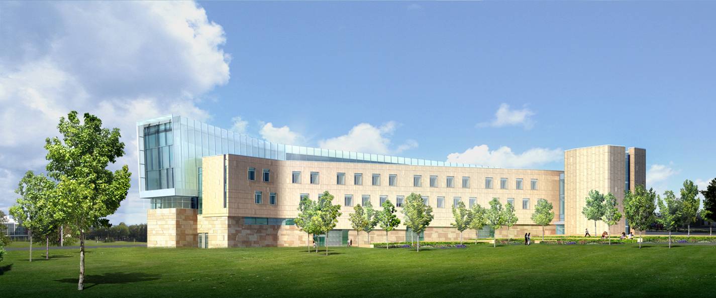
| Rear of the building. All renderings courtesy of Polshek Partnership Architects. |
Building Name: The New Dickinson School of Law – Katz Building
Building Location: 651 Bigler Road, University Park, PA 16802
Building Occupant Name: The Dickinson School of Law faculty and students.
Type of Building: Higher Education
Total Square Footage: 113,000 SF
Number of stories above grade: 3 at the west end, 4 at the east end
Total Levels: 5
Project Team:
Owner – The Office of the Physical Plant <Penn State University>
CM – Gilbane Building Company <http://www.gilbaneco.com>
Architect – Polshek Partnership Architects <http://www.polshek.com>
Engineers (MEP) – Flack & Kurtz <http://www.flackandkurtz.com>
Engineers (Structural) – Robert Silman Associates <http://www.rsapc.com/index.html>
Dates of construction:
Start: 1/18/07
Substantial Completion: October 2008
Finish (Complete Punchlist): January 2009
Cost: $60 Million (Includes FF&E, architect’s cost, engineer’s cost, CM’s cost, and soft costs)
Project delivery method: Construction Management Agency / CM at Risk Hybrid. This project utilizes a mix of elements from both types of delivery methods. The general conditions estimate for this project has been priced as a lump sum contract which would indicate CM at risk delivery method. In addition to this, Gilbane technically holds the contracts for the subcontractors which would also imply a CM at risk method. However, Gilbane is paid for these subcontracts in a cost plus fee manner which removes most of their actual risk and would imply a CM agency method.
Architecture:
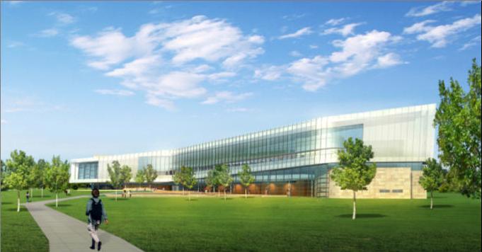
Arguably the most striking feature of the building’s exterior is the prominent architectural curtain wall (CW-4) that covers the south side and part of the north side of the building. In addition to the curving curtain wall, this building will also utilize stone and brick masonry veneer that will differ from the standard brick used on most new building projects on the University Park campus.
The building’s interior features a number of other amenities to improve the building (both in aesthetics and function). The functional features include a large auditorium in addition to classrooms, a mock courtroom, a reheat snack bar, and a legal library. The aesthetic highlights of the interior include exotic wood veneers (European Red Elm and Anigre), slate accents, and curving and tilting interior walls and ceilings.
The major code book used for the design of this building was the International Building Code 2003.
The zoning designation for this project is UPD which is the University Planned District.
The building is enclosed by 7 different styles of curtain walls. These curtain walls curve, bend, and tilt. They feature heat treated/tempered insulated glass with painted aluminum mullions.
While a large part of the building’s exterior is covered by curtain walls, there is also a significant amount of brick and stone masonry. The exterior sandstone veneer wraps the lower part of the building below the main curtain wall and the lower half of the back side of the building. The brick used for this project can be seen on the rear of the building above the sandstone veneer. As mentioned earlier, this brick is of special interest because it is not the standard brick used on Penn State projects. It is a light tan that required special approval from the University’s President Graham Spanier.
Because this building utilizes a prominent curtain wall that visually defines the top of the building, a parapet wall is used at the roof level. This effectively hides the roof from view. Therefore, the roof could be an ideal location to place roof gardens which can help the building thermally and contribute to its LEED credentials. The roof gardens sit on 4” rigid Styrofoam insulation and constitute most of the roof area on the building. A TPO (Thermoplastic Polyolefin Membrane) roof membrane is adhered to 3” insulation boards on top of the steel deck and makes up the rest of the roof area. Both of these elements will help to insulate the law school.
Construction:
This project required some demolition work before site excavation could occur. There was an existing parking lot on the site which had approximately 1200 parking spaces. This substantial parking lot along with the light poles all needed to be demolished.
After the demolition work, excavation began on site. One of the interesting problems that arose once excavation started was related to a large sinkhole that ran under the building’s foundation. This sinkhole was not known before excavators started work. Because the clay soil would not be structurally sound to support the building foundations the workers dug out all of the clay soil and filled the void where the clay was with concrete. This effort required a substantial amount of concrete. (Approximately 1650 yards)
After the soil problems were dealt with, it was possible for construction to start. The construction started with the foundations which consisted of spread footers and grade beams. The cast-in-place foundation walls were formed, reinforced, and poured and then the lower level slab on grade was placed. All foundation walls were poured except for the west side of the south wall. This wall would be left open while the construction ramp was in place.
After the substructure was constructed, the steel superstructure erection commenced. The steel started being erected on the east end of the building and work westward. As steel columns and beams were erected, steel deck was installed, any concrete embeds were placed, and concrete slabs on metal deck would be poured.
After the superstructure was erected, the building enclosure was the next step. The curtain walls and masonry walls were built. After the enclosure had been completed, the interior walls were framed, drywall was hung, and FF&E work began.
Structural:
The building’s substructure is comprised of concrete spread footings and grade beams supporting cast-in-place concrete foundation walls. The superstructure is a steel skeleton with composite slabs on metal deck. While there are many different sizes of W-shapes incorporated in the building plan, the most common sizes are W8x13, W12X19, W10X33, and W10X49.The slabs range in thickness from 2.5” lightweight 4000psi slabs on 2” 18 gauge steel deck with 6x6-W2.0xW2.0 welded wire fabric up to 4.5” normal weight 4000psi concrete on 3” 16 gauge steel deck with 6x6-W2.0xW2.0 welded wire fabric. The steel bays vary greatly in size. By the nature of the building’s curving footprint, it is difficult to maintain one typical bay size throughout this project. The largest bay used in this project is 10’-8”x27’6”.
Mechanical:
The building’s environment is regulated by 7 air handling units that are fed from the campus utilities. The 7 units range in size from 2,500 CFM to 26,000 CFM. The units also vary greatly in cooling and heating capacities. The smallest has 89,000 Btu/Hr cooling and 109,000 Btu/Hr heating capacities. The largest capacity is 972,000 Btu/Hr cooling and 1,128,000 Btu/Hr heating.
Variable Air Volume (VAV) control units are used to control temperature in each room. These allow for the supply air temperature to remain relatively constant throughout the whole building and will use differing amounts of air flow to change room temperatures. The return air system in this building uses predominantly ceiling plenum space to direct it back to the air handlers. Air is supplied to the rooms and then exhausted via a small return duct that directs the air into the ceiling plenum in the long corridor through the building.
Lighting / Electrical:
The Law School is fed by a 1500kVA 480Y/277 power supply. That power supply is distributed to a series of distribution panel boards which in turn feed the room panel boards. The building also utilizes a 40,000 Watt uninterruptible power supply (UPS) power system for potential electrical system failure.
There is a wide variety of light fixtures used on this project. There are fluorescent (T5 and T8), incandescent, HID (T4.5 Ceramic Metal Halide), and Light-Emitting Diode (LED) light fixtures used. These fixtures vary in form from track lighting, to recessed lighting, to ceiling mounted, to cove lighting, to accent lighting. One of the more interesting light fixtures used is a curving fixture that uses numerous compact fluorescent lamps. This allows it to be placed in coves (in the Legal Library, for example) that have curved corners and will help eliminate cold spots from the cove lighting.
Other Building Features:
This project will utilize fully sprinklered fire protection. The sprinklers are fed by a 6” siamese fire department connection and also an 8” incoming line from Penn State’s utilities. The fire department connection is located on the Bigler Road extension to the west of the building.
The building utilizes four hydraulic elevators. Three of these (PE-1, PE-2, PE-4) are passenger elevators with a 2000Lb capacity. The fourth elevator (SE-3) is a service elevator with a 4,500Lb capacity. All elevators will stop at all floors with the exception of PE-4. PE-4 (located on the east side of the building) will stop at every level except the lower level.
The telecommunications in this building consist of fiber optic cables that are fed to room 005G Server Room where the fiber lines are terminated. 24 Category 6 lines are then run to the telecommunications rooms located on the east side of the building and just south of the building’s core. (The “core” of the building refers to the northernmost section of the building that contains PE-1.) The Category 6 lines are then distributed from the equipment racks in the telecomm. rooms to each individual room in the building via a 18” basket cable tray that will follow the building’s main corridor.
● The Capstone Project Electronic Portfolio (CPEP) is a web‐based project and information center. It contains material produced for a year‐long Senior Thesis class. Its purpose, in addition to providing central storage of individual assignments, is to foster communication and collaboration between student, faculty consultant, course instructors, and industry consultants. This website is dedicated to the research and analysis conducted via guidelines provided by the Department of Architectural Engineering. For an explanation of this capstone design course and its requirements click here.