|
|
| Building Statistics |
| Name |
New Science and Technology Center |
| Location |
Philadelphia, PA |
| Occupants |
Chestnut Hill Academy Faculty and Students |
| Occupancy Type |
Educational (group E) |
| Size |
26, 870 SF |
| Stories |
2 |
| Project Team |
| Associate Architecture: |
Krieger & Associates, Philadelphia, PA |
| Architect of Record: |
Lilley Dadagian Architects, Lexington, MA |
| Contractor: |
Turner Construction, Philadelphia, PA |
| Lab Designers: |
Jacob Consultancy (formerly GPR), Tarrytown, PA |
| "Green" Design Consultant: |
M2 Architecture, Philadelphia, PA |
| Structural Engineers: |
Roome & Guarracino, LLC, Somerville, MA |
Mechanical Electrical Plumbing |
Engineers: |
Bruce E. Brooks & Associates, Philadelphia, PA |
| Civil Engineers & Landscape: |
Cairone & Kaupp, Philadelphia, PA |
|
| Construction Dates |
Nov-2007-Nov-2008 |
| Cost |
9.6 Million |
| Delivery Method |
CM at risk |
| Architecture |
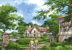
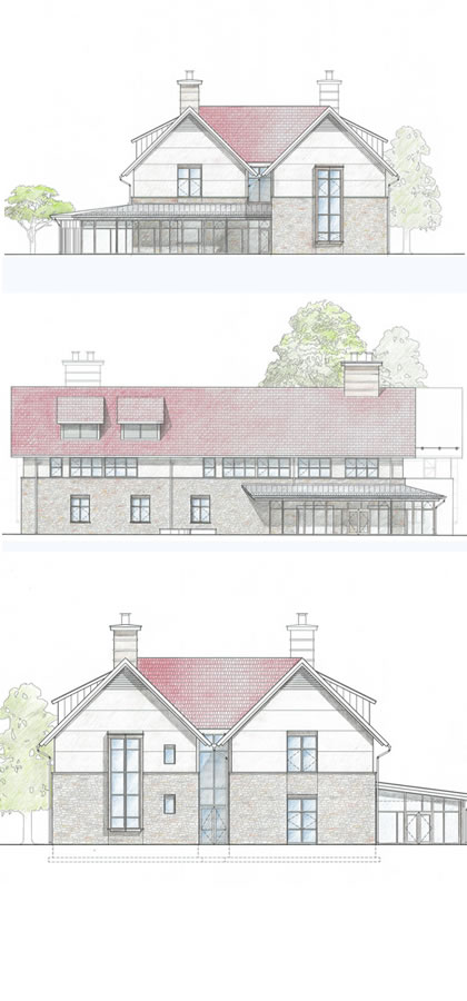
The primary function of the new Science and Technology Center will be to house seven new classrooms and labs and a new faculty suite. The building has two stories with the first containing a K-2 and a 3-5 classroom, a robotics lab, and a physics lab. The second story will contain a biology lab with two other multi-purpose labs, as well as a faculty suite. The main building material for the center will be masonry to match the existing buildings already on the campus. The eastern and southern sides of the building will have a glass-enclosed lobby providing a main entrance to the building. Outside of the lobby will be an outdoor classroom that is created by extending the lobby floor past the glass walls. The roof of the building will include a built in photovoltaic array as well as a wind turbine. |
| Codes |
Based upon 2006 edition of the IBC with 2007 City of Philadelphia amendments as well as the City of Philadelphia Plumbing Code |
| Zoning |
Council District #8, The Philadelphia Code |
| Building Envelope |
The roofing system is composed of three different types: asphalt shingles, preformed metal roofing, and a single-ply membrane roofing system. The asphalt shingles will be the main roofing material for the building with the single-ply membrane taking up a small part. The metal roofing will be used for the enclosed entrance lobby on the first floor. The exterior wall system is comprised of three wall types: a masonry wall, a cavity wall, and a glass curtain wall. The masonry wall is on the lower half of the building and is made with six-inch stone on the exterior, followed by a mortar net, rigid insulation, air/vapor barrier, dense glass, and GWB. The cavity wall has a stucco exterior followed by galvanized Z-furring, rigid insulation, drainage board, air/vapor barrier, dense glass, and GWB. The glass curtain wall is located around the exterior of the entrance lobby with the masonry wall acting as the interior wall for the lobby. |
| Stuctural |
There are three foundation/first floor slabs at the New Science and Technology Building. They all have a veering pressure allowance of 1.5 tons per square foot and are 5” SOG with 6x6 W2.9xW2.9 WWF reinforcement. The outdoor patio slab is the lowest slab with the lobby and first floor 3” and 5” higher, respectively. The exterior columns are primarily W8x35 on the southeast side of the building and W8x31/40 on the northwest. The interior columns range from W8x35 to W8x48. The lobby curtain wall system is supported by HSS 5.0x1/4 AESS posts. The second floor framing consists of W18x35 exterior girders with W18x40-46 beams framing into the interior W18 x40 girders. The attic exterior girders are W18x71-35 with W18x40-46 beams framing into W24x84 interior girders. The second floor and attic are 3-1/4” LW concrete with a WWF 6x6 W2.9x2.9 on a 2” deep 20 GA composite steel decks with a total thickness of 5-1/4”. The exterior walls are cavity walls with a 6” stone veneer and a 6” light gauge steel stud. The main roofing system is a 3” deep 20 GA galvanized steel deck with the lobby deck being only 1-1/2” deep. |
| Mechanical |
The New Science and Technology Center is planned to act as an addition to the already existing MEP infrastructure on campus. Power and water (domestic, heated, and fire suppression) will all be supplied from the central plant. A 57.1 ton scroll chiller will be installed remotely for current use, with plans to upgrade to a 144.4 ton unit for use with future developments. The first and second levels will both be supplied by separate AHU’s, AHU-1 and AHU-2, respectively. AHU-1 has a 6,300 CFM capacity and AHU-2 an 8,000 CFM capacity. Both are VAV units with an economizer and energy recovery in the form of a variable speed heat recovery wheel. The initial supply air setpoint from each AHU is 55 F. Once the zones are satisfied, the setpoint will be gradually adjusted to reduce energy use from heating and cooling. The air is supplied to the different zones using a single duct VAV system. The system is run on a user-defined schedule with both occupied and unoccupied modes. During the occupied mode, the cooling setpoint is 74 F and the heating setpoint is 70 F. During the unoccupied mode, the cooling setpoint is raised to 85 F and the heating setpoint is dropped to 65 F. The system is also equipped to monitor zone CO2 levels and override the damper controls to maintain a level of 500 PPM. A new 6” gas main has been provided by Philadelphia Gas Works as well. |
| Electrical |
The electrical system is powered by a 480/277v feeder from the neighboring Inn Building. The Inn Building will also have a new 400A/3P circuit breaker added to the existing 480/277v switchboard. The electrical systems will be controlled from the electrical room on the first floor, which will contain a 480D-208Y/120v transformer, a 480/277, 3f, 4W main distribution panel, and a data rack, among several other control panels. All conduits will be run underground through the floor slabs. All receptacles will be mounted flush with surfaces, except in the robotics lab where the ceiling receptacles will be surface mounted due to the exposed ceiling. The labs will all include specialty workstations, each with 8 power and 2 voice/data receptacles. The stations will also include sinks and The PA system will be installed by a separate PA contractor and is not the responsibility of the electrical contractor. The owner will also be responsible for installing and furnishing two photovoltaic arrays and a wine turbine on the roof. |
| Lighting |
All exterior site lighting will be controlled via photocell on/off time clock processor located in the electrical room. The classrooms and hallways are lit with 1’x4’ pendant hung direct/indirect luminaries, each with two 32 watts lamps. Fluorescent wall washers with two 32 watt lamps will light the whiteboards in each classroom. The lobby has 6” diameter compact fluorescent downlights with one 26 watt lamp each. Each classroom will have a daylight harvesting system that will be sensor controlled with on/off settings. The maximum sensor time out is 30 minutes with a manual override switch located in each room. |
| Construction |
The New Science and Technology Center is a CM at risk project. The Chestnut Hill Academy is under direct contract with the designers. One special feature of the site is the porous pavement constructed of 2” of concrete and 4” of gavel on top of a stable and non-yielding subgrade. The porous sidewalks also include a 1” choker coarse between the concrete and gravel. All porours pavement will drain into the stormwater system. The site also has two 18” deep raingarden modified soil/plant mixed planters. All of the labs will include visual display boards and the robotics lab will also have a electronic scavenger arm. |
| Engineering Support Systems |
There are no requirements for the fire rating of the structure of the New Science and Technology center (PBC Type IIB). However, any place location where fire rated partitions are supported by the structure will be required to meet the apporopriate fire ratings required for combustible materials. All of the locations requiring the use of fireproofing utilize sprayed on fireproofing. The building is also equiped with a sprinkler system in accordance with NFPA 13. The elevator is required to comply will all related regulations, including NFPA and ANSI codes. |
|
 |