Building Name: Center for Drug Evaluation and Research Office Building 2
Location: White Oak, MD
Building Occupant: FDA
Size: 330,000 gsf
Stories: 6stories/85ft
Project Team:
Owner:
GSA/FDA (General Services Administration/Food and Drug Administration)
Architect:
Kling Stubbins
2301 Chestnut Street
Philadelphia, PA 19103
http://www.klingstubbins.com/
Architect:
RTKL Associates Inc.
901 South Bond Street
Baltimore, MD 21231
http://www.rtkl.com/
Structure/Interior/Mechanical/Electrical:
RTKL Associates Inc.
901 South Bond Street
Baltimore, MD 21231
http://www.rtkl.com/
Site/Civil/Environmental:
Greenhorne & O’Mara, Inc
http://www.g-and-o.com/main.asp
Topographic Surveying:
A. Morton Thomas & Associates, Inc
http://www.amtengineering.com/
Acoustics:
Shen Milson & Wilke, Inc.
3300 N. Fairfax Dr., Suite 302
Arlington, VA 22201
http://www.smwinc.com/index.html
Architectural:
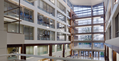
The Center for Drug Evaluation and Research Office Building 2 (CDER 2) is a new six story office building for the FDA. CDER 2 is composed of two separate office wings (see key A & B) connected by an atrium that reaches through the center of the building.
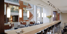
The first floor of the atrium is the main entrance which rises up the full six stories, creating a dramatic entrance to CDER 2. Opposite the entrance is the main elevator lobby; bridging the entrance and elevators are the security desks and offices, as well as a few more welcoming spaces such as the large reception area and coffee bar. As the elevators rise, they empty into lobbies which are accessible to both office wings.
The floor plans for both office wings A and B are fairly consistent throughout all levels. Due to the geometry of the office wings, being long and narrow, most offices have a view of either the exterior or the grand interior lobby. The offices themselves are also quite consistent in size and are typically separated by partition walls consisting of gypsum board on metal studs.
The primary exterior wall system, the one used on office wings A and B, includes a brick façade which anchors into the structural concrete beams and supporting CMU wall. The interior of this system consists of gypsum board on metal studs. Punch windows, typically about six feet wide by seven feet tall, occur at each office location
The brick façade is occasionally accented by an aluminum panel and mullion system. The mullions anchor into a metal stud framing system, whose interior is also gypsum board. The aluminum panels are usually utilized near areas of egress that are visible from the exterior: stairs, elevators, and exits are a few examples.
The atrium’s curtain wall system stands out from the rest of the building and draws people to the entrance. The curtain wall consists of low-e insulated glass, supported by horizontal and vertical aluminum mullions which anchor into the structural concrete. Almost the entire atrium utilizes the system, even the sides that are framed in by the office wings A and B. This provides excellent views both from the atrium to the outside and from the many offices that overlook the atrium.
Structural:
Lateral and Gravity System
With a concrete moment frame, the lateral and gravity system of CDER2 are same. A uniform grid of columns with deep exterior beams and a two-way flat slab, establishes the structural system.
There are two main column geometries: the interior square columns and the long and lean exterior columns. The interior columns are about 24”x24” (600mm x 600mm), 4000 psi (28MPa) concrete. In addition to being found at the interiors of the office wings, these 24”x24” columns are also found where the wings are bordered by the atrium. The exterior columns are about 16”x58” (400mm x 1460mm) and are also composed of 4000 psi concrete. Reinforcement within the columns is fairly consistent with #9 bars, but varies in arrangement and number depending on the loading and level.
Consistency is a regular theme in CDER2; this is no different for the exterior beams. A 16”x50” (400mm x 1260mm) beam of 4000 psi (28 MPa) concrete exterior beam is quite regular. As mention previously, these beams serve the purpose of gravity as well as lateral loads. The only noticeable change in beam design is at the office wing/atrium interface; here a wider, but shallower beam of 24”x21” (600mm x 530mm) can be found. Reinforcement for the beams ranges anywhere from #4-#9 ASTM GRADE 400 steel bars, throughout the top, bottom, and side faces of the members.
Floor System
CDER2 utilizes a two-way flat slab floor system with drop panels located at the interior columns. Structurally, bay sizes are very typical and almost square being about 30’x31’. The floor slab itself is made up 9.4 inch (240mm), f’c = 4000 psi (28 MPa); at the drop panels, the slab gains an addition seven inches (180 mm). Void of interior beams, the reinforcement of the two way slab consists of primarily of #4-#7 ASTM GRADE 400 steel bars. An even distribution of reinforcement is regular throughout most of the slab; multiple layers of reinforcement are common near columns as well as the deep exterior beams. While there are little variations in the floor system, these differences primarily occur around the areas of egress and in mechanical spaces.
The primary roof follows a similar framing system as the other floors. However, w-shapes supporting metal decking provides the structure for the rising atrium roof; W310 and W360 (mm) are the ordinary beam sizes.
Mechanical:
The air supply for CDER 2 is provided through an underfloor low-pressure air plenum. There are five rooftop air handling units responsible for supplying 100% outdoor air, (3) 990 L/s, (1) 1133 L/s, and (1) 236 L/s. Additionally, there are five return air handling units, all around 1500 L/s. The supply air is directed to each floor by 700x600 mm ductwork. The air is then directed to the supply floor diffusers through the distribution plenum box located beneath each floor.
There are seven additional indoor air handling units located in the basement. They service the atrium, mechanical and electrical rooms, and the basement.
The hot and cold water supply enters CDER 2 in the basement from the tunnel that connects CDER 2 to the other buildings in the campus. From the tunnel, the water is direct to the six water pumps located in the basement of wing B; the three cold water pumps are 10KW pumps capable of 32.2 L/s, while the three hot water pumps are 5.4KW pumps capable of 17.3 L/s.
Fire Protection:
CDER 2 utilizes a wet sprinkler system for fire protection; the system is completely separate from the function of the other mechanical systems. The water supply for the sprinkler system is supplied from the same tunnel that connects CDER 2 with the campus. A separate room in the basement holds the 56 KW, 47 L/s fire pump and controlling equipment. Each level has the wet sprinkler system located in the main corridor of each office wing, as well as the atrium bridges connecting the wings.
Electrical:
The most typical lighting in CDER 2 occurs in the offices; wall mounted and pendant mounted 2400mm long fluorescents are utilized. Typically the fluorescent lamp has a color temperature of 3500K and a CRI of 85. The fixture housing consists of a steel rectangular profile with a semi-specular aluminum reflector. The lighting in the main corridors of the office wings primarily consists of a low profile compact fluorescent downlight.
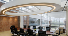
The elevator lobby employs a few types of lighting systems. The lobby itself is primarily lit by a 0.9meter diameter circular recessed fluorescent fixture with a thick white acrylic lens; a compact fluorescent downlight within a frosted glass cylinder is also used. Additionally, two types of accent lighting are utilized in the lobby; one is a low voltage, incandescent wallwasher with a glass lens, which directs its light onto the wall adjacent to the elevators. The other is a low voltage, adjustable accent light recessed within the raised floor. Its light is directed on the wall of the conference room that faces the lobby.
Similar to the mechanical supply, the primary feeders enter CDER 2 through the tunnel which connects to the campus. Each office wing has its own transformer; wing A utilizes a 2000 KVA forced air, three phase cast coil dry-type transformer that steps the voltage down from 13.8 KV to 480\277V. Wing B utilizes a 1500 KVA natural ventilation, three phase cast coil dry-type transformer that steps the voltage down from 13.8 KV to 480\277V.
|
|