 |
Johns Hopkins Hospital New Clinical Building Baltimore, MD |
| Home |
| Student Bio |
| Building Statisics |
| Thesis Abstract |
| Technical Assignments |
| Thesis Research |
| Thesis Proposal |
| Presentation |
| Final Report |
| Reflection |
| Sr. Thesis eStudio |
Building Statisics
Building Name
Johns Hopkins Hospital New Clinical Building
Location
600 N. Wolfe Street
Baltimore, MD 21287
Building Occupant Name
Johns Hopkins Hospital
Size
Adult Tower (Includes Connector) = 960,000 square feet
Childrens Tower = 540,000 square feet
Total Size of Medical Facility = 1,500,000 square feet
Number of Stories
Adult Tower:15 stories above grade, 3 stories below grade
Childrens Tower: 15 stories above grade, 2 stories below grade
Connector: 8 stories above grade, 2 stories below grade
Project Team
| Owner | Johns Hopkins Hospital | www.hopkinsmedicine.org |
| General Contractor | Clark/Banks, A Joint Venture | |
| Architect | Perkins + Will | www.perkinswill.com |
| Structural Engineer | Thornton - Tomasseti | www.ttengineers.com |
| MEP Enginer | Bard, Rao + Athanas | www.brplusa.com |
| Civil Engineer | Rummel, Kleeper & Kahl, LLP | www.rkk.com |
| Telcommunications Consultant | Smith Seckman Reid, Inc. | www.ssr-inc.com |
| Life Safety & Security Consultant | Schirmer Engineering | www.schirmerengineering.com |
| Vertical Transportaton Consultant | Zipf Associates, Inc. | N/A |
| Medical Equipment Consultant | Equipment Planners, Inc. | www.equipmentplanners.com |
| Cost Estimator Consultant | Davis Langdon | www.davislangdon.com |
Dates of Construction
October 2006 – December 2010
Cost
GMP Contract of $573 Million
Project Delivery Method
Design-Bid-Build
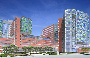
Architecture
The medical facility features two, connected towers – one tower for the children’s hospital and the other for the adult, cardiovascular and critical care hospital. The facility will include 355 adult beds and 205 pediatric beds, 33 operating rooms, 42 radiological suites, 13 non-invasive treatment areas, 16 gastrointestinal and pulmonary diagnostic and treatment areas, and 96 emergency treatment rooms.
Codes
Maryland Building Performance Standards/October 2001
International Building Code/2000
National Electrical Code/1999
National Fuel Gas Code/1999
International Mechanical Code/2000
National Standard Plumbing Code/2001
International Property maintenance Code/2000
International Fire Code/2000
International Energy Conservation Code/2000
Zoning
Hospital
Historical Requirements
No historical requirements
Building Envelope
The building envelope is comprised of two main systems – precast and a curtainwall. The precast accounts for 201,000 sq. ft. or 43% of the building envelop. The design is a 6” thick concrete panel with a brick veneer. There are 1,350 pieces weighting as much as 32,000 lbs. that are being manufactured by Artex Systems, Inc in Toronto, Canada with the brick being supplied from Germany. Erection is by the steel erector using 2 Comansa Model 21LC550 tower cranes, 250 ton Kobelco luffer crane, and a 150 ton Link-Belt crawler crane. The panels are delivered by truck just in time for erection and connected to the building structure through bolted connections.
The aluminum unitized curtain wall system accounts for 275,000 sq. ft. or 57% of the building exterior. The design uses a random pattern of various colors of glazing on the south face of the Children’s Tower to offer an architectural appeal. The detail design is by the subcontract, Harmon Inc. which is installing the system using a 150 ton mobile hydraulic crane. Just-in-time delivery of preassembled curtainwall sections are connected to the building structure with halfin anchors that are embedded in the concrete slabs.
The medical facility has a total of 9 roof levels. 5 roof tops where mechanical equipment is located uses a single ply, fully adhered roofing membrane on ½” recover board and 4” of high density insulation. The other 4 roofs utilize a green roof system.
Foundation
The building is primarily supported by 275 caissons ranging from 3’-10’ in diameter. 3,000 psi concrete was used in the caissons which varied in depth from 30’ to 50’. A traditional strip footing supports the perimeter. Grade beams are used at high load areas such as vehicle rams and high axial loads from columns near large spans.
Structural System
A structural steel frame with a CIP composite floor system supports the building. A total of 12,500 tons of steel are used in this system with a typical bay size of 28’-8”, 16’ floor-floor heights from levels B3-8 and 14’ floor-floor height from levels 9-roof. The shear system is a braced frame system with a few moment connections near the cantilever. The 18’-4”W x 143’-4”L radial cantilever is supported from level 4 to the roof. The largest steel member is a 57’-4”L x 72”D I-shape plate girder located on level 3 of the Ambulance Bay area in the Children’s Tower.
The CIP composite floor deck ranges from 5 ½” - 11” thick normal weight reinforced concrete slabs from levels B3-8 to 4 ¼” – 6 ¼” thick light weight reinforced concrete slabs from levels 9-roof. No formwork was required during placement of concrete. Primary method of placing was by a pump truck using a slick line. In some cases a buggy was used for smaller pours where it was not feasible to bring in a pump truck.
Masonry
There is no masonry included in the scope of work.
Mechanical System
An offsite central plant supplies chilled water and high pressure steam to the hospital on level B3 in the south-west corner of the Adult Tower with a 24” chilled water supply/return and a 8” high pressure steam supply/return. The main mechanical room is located on floors 6 and 7 where there are 19 air handling units ranging from 11,000-133,000 cfm. The AHUs provide 50⁰F cooled air at all times that is distributed throughout the building to variable air volume units located in each room. The VAVs reheat the air to the temperature controlled by the room’s thermostat. All of the air conditioning system uses rectangular and round ductwork to distribute the conditioned air.
The high pressure steam is used for heating hot water through shell and tube heat exchangers on the 6th floor. A loop of hot water is supplied to all floors that is used in the VAV reheat coils and for hot water supply. High pressure steam is also used for humidifying air and sterilizing hospital equipment.
Domestic water is supplied to the building via 2-8” lines. The main supply is at the north-east corner of the Children’s Tower on level B1 with a redundant supply at the south-west corner of the Adult Tower on level B1. The water is then distributed throughout the building as needed.
There is a large offsite storage tank that supplies oxygen gas to all patient rooms, operating rooms, and exam rooms. Medical air and vacuum are produced on level 6 in the mechanical room. There is a very sophisticated control and alarm system that manages all of the medical gas supplies.
Electrical System
Power is provided by 2-15KV, 3 phase feeders that are located on level 1 in each tower. The primary electrical room is located on levels 6 and 7 where the power is stepped down to 460V, 3 phase by 3 transformers on level 6 in each tower and 2 transformers on level 7 in each tower. The 460V, 3 phase is distributed to 2 electrical rooms per floor of each tower where the power is then stepped down to 120/208/240/277V, 3 phase. Finally the power is distributed to localized electrical closets around the floor where it is then supplied to the rooms. Power distribution is by copper and aluminum wire and bus ducts that carry high voltage power.
The offsite central plant houses emergency generators to supply the hospital with power in case of emergency. However, there are uninterrupted power systems (UPS) located in the main electrical rooms to provide immediate power in the case of a power outage. The UPS system uses a large quantity of batteries that will provide power for a short amount of time until the emergency generators can reach capacity.
Fire Protection System
The primary fire protection system is a wet sprinkler system that will provide fire suppression in case of a fire. A pre-action sprinkler system is used in the electrical rooms so that sprinklers are not accidently set off which could cause major damage to the electrical system. Fire pumps are located on level B2 in the Adult Tower.
Transportation
There are two elevator cores in the building, one in the Adult Tower and one in Children’s Tower. The Adult Tower’s elevator core has 6 passenger, 2 patient, 2 trauma, 2 soiled, 2 clean, and 1 service transfer elevators that run the entire height of the building. The Children’s Tower has 5 passenger, 2 patient, 2 trauma, 1 soiled, 2 clean, and 1 service transfer elevator that runs the entire height of the building. The elevator machine rooms are located on the penthouse levels of both towers.