Structural System
Gravity Framing System
Typical office floors are 3¼” light weight concrete fill on a 3” 18 gage Verco W2 Formlock composite steel deck for a total thickness of 6¼”. The central slab located at the core of the building is elevated 16½” above the surrounding floor level. Columns supporting the composite deck are standard structural steel wide flange sections. Mechanical areas are similar to the typical office floors with the exception of normal weight concrete fill in place of the lightweight fill on composite metal deck. The roof system on the tower portion of the structure consists of the same composite steel deck system as the typical office floors. The green roof on the Key System portion of the structure is also composite metal deck but the sizes of the supporting columns are larger in order to support the additional weight of the plantings.otings.
Lateral System
Wind and earthquake forces are resisted by a dual system composed of steel Special Concentric Braced Frames located around and across the building core and Special Moment Resisting Frames (SMRF) at the building perimeter. Braces are wide flange members with welded connections. Diagonal bracing member sizes range from W12x96 to W14x132. Member sizes of the moment resisting frames range from W24x94 to W24x207. Moment connections are Welded Unreinforced Flange type with welded webs (WUF-W). Columns supporting members of the Lateral Force-Resisting System (LFRS) are W14x730 with 3½” x 18” stiffener plates between flanges on both sides.otings.
Foundations
The main tower of the building is supported by 110 ton, 14”-square, driven prestressed precast concrete piles beneath a reinforced concrete mat foundation. The structure utilizes 117 existing 14” square piles and requires 334 new 70’-0” long prestressed concrete piles. The concrete mat slab is 5’-9” thick with #11 bars spaced at 12” O.C. each way on both faces. The remaining portion of the foundation is a 9” thick reinforced concrete slab with #5 bars spaced at 12” O.C. Framing within Key System portion of the structure is supported by 6’-0” square spread footings.
Construction
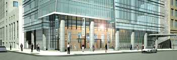
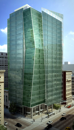
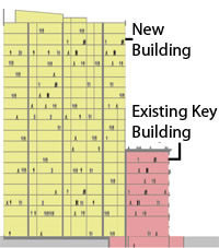
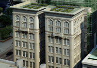
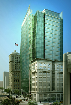
The 1100 Broadway project is currently in design development phase. Construction is scheduled to begin in June of 2010 with completion intended for December of 2011. The project delivery method is design CM-at-risk-bid-build with the CM providing preconstruction services. A special consideration during the construction phase will be preserving the façade of the Key System building, which currently resides on the future 1100 Broadway site, and incorporating it into the construction of the new tower. Through the adaptive reuse of the façade the floors on levels ground through 8 of the main tower will be aligned with the Key System building floors.
Mechanical
1100 Broadway features an underfloor air distribution (UFAD) system which delivers conditioned air at low velocities from the floor without creating drafts that traditional duct systems often produce. This allows for individual temperature control resulting in all around comfort for the building’s occupants. The system is much more efficient than conventional HVAC systems and falls in line with the building’s sustainable design goals. Two 60,000 cfm air handler units (AHU) located on the Mezzanine level serve levels 3 through 9. A 50,000 cfm AHU and a 100,000 cfm AHU are located on the Penthouse level and serve levels 10 through 20. There are approximately twenty perimeter heating elements per floor. A single 650 ton chiller (dual-compressor) system located at the penthouse level supplies air to the penthouse AHUs. A multiple boiler system and a multiple cooling tower system are also located on the penthouse level.
Electrical
Power is supplied to the building through three main utility bus ducts. One 4000A, 480V, 3 phase, 4 wire main bus duct supplies power to a 4000A, 480Y/227V, 3 phase, 3 wire main switchboard. This switchboard supplies power to all floors through two 1600A, 480V bus ducts. Each bus duct feeds into a high voltage panelboard at each floor level which is responsible for equipment and lighting panel loads. The high voltage panelboard feeds into a 75KVA or 112.5KVA transformer which supplies power to a low voltage panelboard responsible for receptacle and low voltage lighting loads.
One 4000A, 480V, 3 phase, 4 wire main bus duct supplies power to a 4000A, 480Y/277V 3 phase, 3 wire main switch board responsible for supplying power to the elevator and emergency power systems. The emergency power system is turned on by a 2000A automatic transfer switch.
One 2000A, 480V, 3 phase, 3 wire main bus duct supplies power to a 1200A, 480Y/277V main switchboard which provides power to the fire pump and a 1200KW/15000KVA emergency diesel generator.
A 60KW photovoltaic array mounted to the sloped penthouse roof is connected to an inverter at the machine room level and tied into an equipment panelboard.
Lighting
The façade is made of high performance glass which allows a significant amount of daylight to enter the building and naturally illuminate the interior spaces. Light shelves located on the exterior of the south façade shade the most direct sun and reflect light to spaces deeper within the building. Dimmable ballasts measure the amount of natural daylight in the building and automatically adjust the electric lighting accordingly to save energy. Lights near the windows will be dimmer than those farther away. Lights also employ motion sensors and turn off automatically when no occupants are present in the building.
Fireprotection
The building is fully sprinklered with automatic sprinklers located on each level. Smoke and fire alarm systems are in place to warn occupants of a fire. There are three fire department valve connections at the building perimeter, one on the roof level and two at the ground level located on the North and East sides of the building. There is a firemen’s control room at the ground level on the Southeast end of the tower portion of the building. A 15,000 gallon fire protection water storage tank and a 200 HP fire pump are located on the basement level.
Transportation
There are seven occupant elevators and one service elevator located at the center core of the building. Elevators 1-3 serve levels 2 through 8 and elevators 4-7 serve levels 9 through 20. The service elevator has access to all levels. There are two main stairs that run the entire height of the building. One set of stairs is at the South end of the tower portion of the building and the other set of stairs is at the north end of the building core. An additional set of stairs on the north end of the building runs from the ground level to level 2.
Telecommunications
A total of twenty 4” telecommunication conduits incoming from the street feed into the telecommunication backboard at the basement level. Eight sleeves run from the basement telecommunication room to the first floor telecommunication room. Six 2” conduits run below the raised floor space for levels 2 and 3. For levels 4 through 20 eight 4” conduit sleeves stub-up 6” above and below the slab and provide bushings at both ends.
Special systems/Unique aspects of the building
In the building’s attempt to achieve a LEED gold rating upon completion it will utilize a reclaimed rainwater system. A 35,000 gallon tank in the basement will serve to collect rain not absorbed by the green roof on the Key System building. Water will be filtered and treated by a special UV system and can then be used to irrigate the roof garden and flush toilets.
The building will function as a Transit-Oriented Development (TOD) which is defined as a mixed-use residential or commercial area designed to maximize access to public transportation, often incorporating features to encourage transit ridership. This is possible due to its location directly above the 12th Street/City Center BART Station and its access to over 20 AC Transit bus lines that stop within one block of the building providing transportation to the East Bay and downtown San Francisco areas. |