Building Statistics
Building Name: Santa Rosa Junior College Student Center
Location and Site: 400 Burbank Circle, Santa Rosa , California
Occupant: Santa Rosa Junior College
Occupancy: The Santa Rosa Junior College Student Center has a mixed occupancy.
- A-3: Assembly
- B: Higher Education
- F-1: Commercial Kitchen
Size: 66,646 sq. ft.
Number of stories above grade: The building has three buildings above grade plus an attic used to house mechanical equipment.
Project team
Title |
Company |
Address |
Contact Info |
Owner |
Santa Rosa Junior College |
1501 Mendocino Ave. Santa Rosa, CA 95401 |
|
Construction Manager |
Wright Contracting, Inc. |
P.O. Box 1270 Santa Rosa, CA 95402 |
|
Architect |
BSA Architects |
501 Folsom St.,4th Floor San Francisco, CA 94111 |
|
Landscape Architect |
Smith & Smith |
1501 North Point San Francisco, CA 94123 |
|
Civil Engineer |
Brelje & Race |
5570 Skylane Blvd. |
|
Structural Engineer |
KPFF Consulting Engineers |
1160 Battery St. Suite 300 San Francisco, CA 94104 |
|
Mechanical Engineer |
AlfaTech Engineers |
120 Montgomery Street, 715 San Francisco, CA 94107 |
|
Lighting Engineer |
Horton Lees Brogden |
300 Brannan St., Suite 312 San Francisco, CA 94107 |
Dates of construction: 12/3/07 – 11/24/09
Cost: +/- $50,000,000
- Midstate Construction +/- $30,000,000;
- Mechanical, Electrical, Geothermal +/- $20,000,000
Project Delivery Method:Lump Sum
ARCHITECTURE
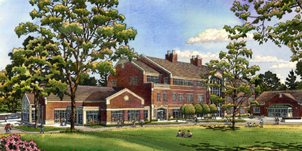
The Santa Rosa Junior College Student Center is the new student center on the Santa Rosa campus. The first of three floors of the center is comprised of numerous offices, a kitchen, student cafeteria, and is highlighted with a three story atrium at the main entrance. The second floor is made up of many more offices along with some classrooms. The third floor is similar to the second floor but also has a computer lab for students as well as study spaces. The attic is reserved for mechanical equipment.
The design of the exterior blends seamlessly with the campus's heritage brick buildings. The curtain wall system consists of a combination of precast concrete beams, brick veneer, and large glass windows on all sides. The sloping roof on the student center is made of concrete tile. Glass fiber reinforced concrete is also used on the roof of the structure. The gutters and downspouts are made of copper. Extensive work is done around the building with pavers (rather than concrete or blacktop) and landscaping and gives students and faculty the opportunity to sit down and relax in a very relaxing and scenic environment immediately outside of the student center.
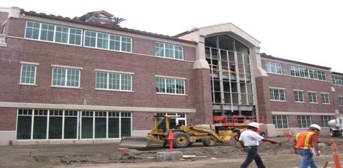
Construction at the main entrance to the Student Center
Major National Model Codes:
- 2001 California Building Code (CBC)
- 2001 California Plumbing Code (CPC)
- 2001 California Mechanical Code (CMC)
- 2005 California Electrical Code (CEC)
- 2001 California Fire Code (CFC)
- NFPA (1995,1999,2000)
- 2001 California Energy Code (CCR)
- 2001 California Elevator Safety Construction Code
- 2001 California Referenced Standards Code
- American with Disabilities Act (ADA)
- ASTM
Zoning: General Commercial
Historical Requirements: None
BUILDING ENCLOSURE
Building Facades
The façade of the student center is mostly comprised of a reddish brown brick veneer that blends in well with pre-existing buildings on campus. Lightly colored precast concrete panels that wrap the building add to its overall architectural appeal. An aluminum framed curtain wall system is used on all facades of the center. The exterior glazing is fixed and includes spandrel glass in some locations. At the main entrance canopy aluminum panels are located both on the interior and exterior. In conjunction with the curtain wall their also exists aluminum corners, fillers, and trim, both interior and exterior.
Roofing
The roofing material used for the student center is concrete roofing tiles. These tiles are mechanically fastened using stainless steel screws and pressure treated wood elevated battens and are brown (California mission blend is the official color) in color. Two layers of 30 pound self adhering asphalt saturated felt are directly underneath the tiles. Flexible flashing is required due to many ridges, penetrations, and elevation changes of the roof. For the few flat parts on the roof, a fully adhered, single-ply, thermoplastic sheet roofing with walkway pads, flashing and sealants is used in conjunction with roofing.
SUSTAINABILITY FEATURES
The most significant example of sustainability in this project is in the use of a Geothermal System. Geothermal power can be used for heating and greatly increases thermal efficiency.
BUILDING STATISTICS 2:PRIMARY ENGINEERING SYSTEMS
CONSTRUCTION:
The project is being delivered using a lump sum method with the architect and construction manager contractually bound directly to the owner. Although the project is not entirely a design-build project, several of the items were bid that way. The majority of the design-build items include, precast, curtain wall, elevators, and fire sprinkler system for the student center. The reason that the project was offered as a lump sum bid was due to the fact that it is very difficult to do a public works bid a design-build. Public contracting laws put constraints on it that are difficult to get around, therefore a lump sum method is more suitable. Private owners have more leeway, but design-build always offers a bit of a struggle to control scope vs. price.
The project was bid in 5 different pieces. Sitework landscaping, building construction, mechanical systems, electrical, and geothermal are the 5 different items that were bid on. Each bid was required to be made out on the Bid Proposal Form that was included in the contract documents and must conform and be fully responsive to the plans, specifications, and all other documents included in pertinent contract documents. Also, each bid was required to be accompanied by cash, a cashier’s or certified check, or a bidder’s bond from an admitted surety insurer. The check or bid bond ensures that the bidder who is awarded the contract will execute the contract documents and provide the required payment, performance bonds, and insurance certificates within 10 days of being notified of being awarded the contract.
On the Santa Rosa Junior College Student Center, the architect works directly for the SRJC. The other design teams on the project work underneath the architect as subcontractors. These design teams include lighting design, civil engineer, structural engineer, graphics, acoustics/audio video, mechanical/electrical/plumbing, landscape architect, and interior design. Since the student center is such a large project, it makes sense to have the design teams contract with the architect instead of the owner so that the architect can have control over everything and avoid any clashing issues. The construction manager on the project, like the architect, holds a contract with the owner. The construction managers job is to oversee the prime contractors and design team but he does not have a contractual relationship with them.
ELECTRICAL:
The Santa Rosa Junior College Student Center gets its power from the 12 kV campus main power service. The power is stepped down from 12kV to 480/277V (power at which the main switchboard runs at) before being stepped down further to 208/120V to be distributed throughout the building by 6 local transformers. The power is further distributed throughout the center by 24 panel boards. The main switchboard is located in the main electrical room on the northeast side of the buildings first floor. Smaller electrical rooms are located on the second and third floors. Along with the electrical rooms, there are also telecommunication rooms on each floor of the building.
A 125kW emergency backup generator is located directly outside of the building in the service yard (northeast part of site). The generator is diesel powered with NEMA 3R base day tank and NEMA 3R sound attenuated housing mounted on a 6” high, 55x123 inch concrete pad. The 12kV transformer, a fire pump with integral automatic transfer switch, booster pump and cooling tower with control panel are also located in the service yard.
LIGHTING:
The 63 types of lighting used in the building run at 277V. Dimmable lighting is a available in the leadership center and also in multiple meeting rooms. Rooms with dimmable fluorescent lights must have a LUTRON, HI-LUME or ECO HI-10 dimming ballast rated at 277V. Interior lighting systems on each floor have separate automatic shut-off controls. Rooms larger than 100SF and greater than .8 watts per SF of lighting are controlled with bi-level switching for uniform light reduction.
MECHANICAL:
The mechanical system for the Student Center is a geothermal heat pump loop with 8” geothermal vault mains (860GMP @ peak load), 5 geothermal circuit loops, and 150 geothermal bore loops making up the system. The geothermal system was installed according to IGSHPA and ASHRAE standards and recommendations. Coordination with the landscape architect and civil drawings is used for irrigation and utilities (existing and new). Extra care is also taken when selecting bore drilling locations as to preserve existing trees on campus. The main mechanical room is 376 SF and is located on the first floor of the center. Each room is served by its own geothermal water source heat pump which range in air flow values from 180 to 2260 CFM. Cooling capacities of these heat pumps also have a wide range of 3.5 to 61.5 MBH.
A 15,000 pound energy recovery unit is located on the second floor of the building. The unit, which sits atop a 6” concrete pad, has a designed 26,000 CFM supply plan along with a 24,500 CFM exhaust fan. The recovery unit runs at 3 phase power and 460 volts.
Two special fans are required in the kitchen/servery areas as exhaust hoods. The units are a combination of fans and grease filtration, which meet exhaust requirements for the kitchen and servery areas of the building on the first floor. Two other fans are used in the kitchen area to provide makeup air. Fans are also located in restrooms, janitor spaces, and the AV room.
Fire Alarm System:
The fire alarm system is an addressable, non-coded, manual initiating system with supplemental detectors for door holders, fire/smoke dampers, and HVAC shut-down. The devices consist of addressable initiating devices and non-addressable notification appliances. The stand-alone system is supervised by a California state approved supervision station. The next nearest building is over 25 feet away and therefore the center is allowed to have a stand-alone system according to code.
STRUCTURAL:
The structural system used for the Santa Rosa Junior College Student Center is structural steel. The floor system that is utilized is a 3 ¼” lightweight concrete on 3” 18 gauge composite decking. The final floor thickness is 6 ¼”. The typical reinforcement for the decking is #3 rebar at 18” on center. The roof system is made up of 1 ½”, 16 gauge decking on steel beams. Flexible flashing underneath concrete tile covers the steel decking on the roof. Typical exterior columns used are W12x50 and W12x40 members. Typical interior columns used throughout the project are W12x58, W12x53, and W12x40. The braced frame on the Student Center is supported mainly by diagonal W10x68 beams connected to structural beams and columns by gusset plates ranging from 1” to 1 ¼” in size.
As far as cast in place concrete utilized on the Student Center project, the foundation, slab on grade, and concrete fill on metal decking comprise the majority of it. The slab on grade is 5” thick with a vapor barrier, 4” rock course, and 6” of select fill below. Reinforcing for the SOG is comprised of #4 rebar at 12” on center at mid-depth along with staggered 30” lap bars. The 18 gauge 3”decking on the second and third floors uses 3 ¼” concrete with #3 rebar at 18” on center. Shear studs are used to tie the concrete into the metal decking and structural steel. Concrete footings range in size from 3x3 to 10.5x10.5 and are located at depths ranging from 1.5 to 2.5 feet below grade comprising the foundation of the center.