
Building Statistics
| General Building Information | ||
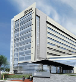
| Building Name: | Roberts Pavilion | |
| Location & Site: | Camden, NJ | |
| Building Occupant Name: | Cooper University Hospital | |
| Occupancy Type: | Patient Care Pavilion | |
| Size: | 320,000 GSF & 51,000 GSF Renovations | |
| Number of Stories: | 10 Above Grade + Basement | |
| Dates of Construction: | August 2006 - December 2008 | |
| Building Cost: | $220 Million | |
| Project Delivery Method: | Design-Bid-Build | |
| Project Team | ||
| Owner: | Cooper University Hospital | |
| Architect/Interior Designer: | EwingCole | |
| Structural/HVAC/Electrical Engineers: | EwingCole | |
| Construction Manager: | Turner/HSC - Joint Venture | |
| Civil Engineer: | Land Dimensions Engineering | |
| Medical Equipment Planning: | Medequip International | |
| Central Sterile Planning: | CT + Associates LLC | |
| Landscape Architecture: | Cairone & Kaupp, Inc. | |
| Elevators: | Zipf Associates, Inc. | |
| Architecture | ||
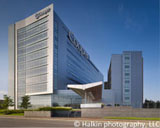
The Roberts Pavilion was designed with the idea that the space should be a “healing garden.” It should be a peaceful and relaxing space. This is evident as you take the main entrance into a two-story lobby that incorporates large skylights that bathe the space in natural light. There is also an abundance of plant life inside as well as natural materials such as stone, wood, and bamboo. These materials give the space its garden type feel and are present throughout the building. |
||
Building Functions by Floor
|
||
Patient care floors are designed with individual rooms around the perimeter of the building, providing optimal views of outside. The interior section of each patient floor is composed of staff offices, nursing stations, and reception. Circulation throughout the building is controlled through the main stair and elevator core located at the southern end of the building. Additionally, adjacent buildings are connected to the pavilion through circulation on the first two floors. |
||
Applicable Codes
The site is zoned I-R (Institutional / Residential) and permits a hospital to be built on the site. No historical limitations were considered during design and construction. |
||
| Building Enclosure | ||
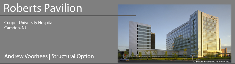
The main façade (shown on the left) is the face of the building visible from the major pedestrian and vehicular routes. It is composed of glass and aluminum panels, and helps to bring together the designs of the adjacent buildings in the complex. The eastern facing façade (shown on the right) is composed of precast concrete and aluminum panels. |
||
  |
||
The roofing system consists of composite decking on the main level. The penthouse roof is composed of steel deck covered with insulation and followed by a water proofing membrane. |
||
Sustainability |
||
| Structural System | ||
Foundation Framing Lateral System |
||
| Mechanical System | ||
The mechanical system in the pavilion consists of a variable air volume system. Air is provided by 9 VAV air handling units. 6 AHU’s are located in the first floor mechanical room and serve the basement through the second floor. The remaining 3 AHU’s are located on the roof and serve floors 3-10. AHU’s on the first floor are 20,000 CFM capacity, roof units consist of (2) 75,000 CFM units and (1) 120,000 CFM unit. Heat for the building is supplied by 3 steam to hot water heat exchangers each with a 600 GPM capacity. Steam is provided by the existing power plant on site. Cooling is supplied by (3) 750 ton chillers and cooling towers located on the roof. Distribution consists of a variable volume primary pumping system. |
||
| Electrical/Lighting Systems | ||
Electric service to the building is a dual 26.4 KV service. Two substations in the building receive 26.4 KV from the 38 KV class switchgear. Electricity is then delivered to each floor after being reduced by the transformers to 480/277 volts. Transformers on each floor drop the voltage to 208/120 for localized appliances. Emergency power is provided by two outdoor 2250 kW, 13,200 volt diesel generators. Each generator has enough fuel for 48 hours of operation. Lighting is provided by energy efficient ballast systems, T8 lamps, compact fluorescent lamps, and color-improved metal halide lamps. Most of the lighting fixtures are powered by the 277 volt, 3-phase system. Automated system controls were used in corridors to change the lighting depending on the time of day. Occupancy sensors and dimming systems were also implemented for energy efficiency. |
||
| Construction | ||
Construction of the pavilion was completed as a joint venture between Turner Construction and HSC Builders. The $220 million project was delivered as a Design-Bid-Build contract. The first phase of the project started with demolition of an existing parking garage on site as well as demolition of parts of the adjacent buildings. New construction started in August 2006 and was completed in December 2008. Adjacent buildings also underwent façade renovations and interior construction as the pavilion was attached to each building. |
||
| Fire Protection | ||
Sprayed fireproofing was applied in the building. Structural members and floors are rated for 2 hours. Interior partitions vary from 1-3 hours by separation distance. To ensure additional safety, a 3 hour rated firewall was constructed to separate the pavilion tower from the buildings to which it is attached. Active fire protection consists of sprinklers that are provided on each floor as well as standpipes in each stair tower. Each standpipe is sized at 250 gpm and 100 psi at the top. |
||
| Transportation | ||
The pavilion tower contains a total of 8 elevators: 4 to serve passengers and 4 service elevators. Passenger elevators have a capacity of 5000 lbs and a speed of 450 fpm. There are 11 stops between the basement and level 10. The service elevators vary in capacity from 6000-8000 lbs and also travel at 450 fpm. One of the service elevators allows access to the roof. All elevators are powered by a 480 V, 3 phase, 60 Hz system. Stair towers at each end of the building provide means of egress within the 200 ft maximum distance from the interior of the building. Clear widths in the stairways exceed the minimum of 44”. Minimum corridor widths were sized based on the occupancy loads determined from NFPA 101. These include 96” corridors in non-ambulatory health care areas and 41.5” door widths in rooms with moving beds. |