 |
||||||||||||||||||||||||||||||||||||||||||||||||||||||||||||||||||
|
||||||||||||||||||||||||||||||||||||||||||||||||||||||||||||||||||
|---|---|---|---|---|---|---|---|---|---|---|---|---|---|---|---|---|---|---|---|---|---|---|---|---|---|---|---|---|---|---|---|---|---|---|---|---|---|---|---|---|---|---|---|---|---|---|---|---|---|---|---|---|---|---|---|---|---|---|---|---|---|---|---|---|---|---|
| proposal | ||||||||||||||||||||||||||||||||||||||||||||||||||||||||||||||||||
| click on image below to view the most recent proposal | ||||||||||||||||||||||||||||||||||||||||||||||||||||||||||||||||||
 |
||||||||||||||||||||||||||||||||||||||||||||||||||||||||||||||||||
| to view revision 1 proposal, posted 01.11.2013, [click here] | ||||||||||||||||||||||||||||||||||||||||||||||||||||||||||||||||||
| to view original proposal, posted 12.11.2012, [click here] | ||||||||||||||||||||||||||||||||||||||||||||||||||||||||||||||||||
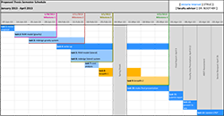
| click on image below to view progress schedule | ||||||||||||||||||||||||||||||||||||||||||||||||||||||||||||||||||
 |
||||||||||||||||||||||||||||||||||||||||||||||||||||||||||||||||||
| structural depth | ||||||||||||||||||||||||||||||||||||||||||||||||||||||||||||||||||
|
gravity | |||||||||||||||||||||||||||||||||||||||||||||||||||||||||||||||||
The gravity system of MTOB shall be redesigned using cellular composite beams and custom girders (in an exposed ceiling). The size of the gravity members will be analyzed in three different ways to ensure its adequacy and efficiency. A RAM model will be created for the new grid and structural system. This will give computer generated sizes for the composite cellular beams. Then plastic analysis will be used to approximate the cellular beam as a Vierendeel truss to analyze its adequacy. |
||||||||||||||||||||||||||||||||||||||||||||||||||||||||||||||||||
| lateral | ||||||||||||||||||||||||||||||||||||||||||||||||||||||||||||||||||
| To stiffen the lateral system, the eccentrically braced frames will be replaced with concentrically braced frames. The existing frames have a link that is 73% the length of the span, which causes the braced frames to act more like moment frames. These will be designed according to ASCE 7-10. | ||||||||||||||||||||||||||||||||||||||||||||||||||||||||||||||||||
| breadth 1: architectural | ||||||||||||||||||||||||||||||||||||||||||||||||||||||||||||||||||
|
An architectural façade redesign is called for to emphasize the structure and to reflect the contemporary style of the offices. New enclosure materials will include metal paneling, spandrel glass, brick, and glass. These materials will allow the building to assimilate with the surrounding architecture while lending a modern feel. A study will be done to anticipate the use of the building materials to impact envelope performance. This will include thermal envelope calculations and look at the potentials for condensationg. The lateral system is now concentrically braced frames. While most buildings try to avoid crossing in front of windows, the lateral bracing will be emphasized directly behind the windows. To facilitate the façade redesign process, a computer model will be made in Revit. The Revit model will contain the structural beams, columns, and bracing underneath the architectural façade. This will give a more realistic impression of how the new enclosure will work with the structural redesign. |
|||||||||||||||||||||||||||||||||||||||||||||||||||||||||||||||||
| breadth 2: mechanical | ||||||||||||||||||||||||||||||||||||||||||||||||||||||||||||||||||
|
Most mechanical systems are simply hung below the structure. However, to allow the ceiling to expose the structure (no hung ceiling), fire ratings require the building to shorten by 5' to a 65' building height. Cellular beam systems are a deeper system, which complicates the necessity to lower the height. In order to meet the height requirement of the IBC, the mechanical system will have to be carefully incorporated into the structure. To complicate the duct system more, the lack of plenum space will require both supply ducts and return ducts, where a typical hung ceiling will use the plenum to collect return air. As part of the mechanical breadth, load and ventilation requirements will be calculated. This will be used to size main duct runs and feeders, making sure that they are small enough to fit through the cells of the cellular beams and the webs of the girders. A typical mechanical duct run plan will be created to show a possible layout of ductwork for supply and return air. |
|||||||||||||||||||||||||||||||||||||||||||||||||||||||||||||||||
| MAE requirements | ||||||||||||||||||||||||||||||||||||||||||||||||||||||||||||||||||
 |
Several of the additional MAE coursework will be utilized in the completion of this thesis. To aid in the analysis, a detailed computer model will need to be modified from the one created for the technical reports (AE 530, Computer Modeling). With the redesign of the façade necessary with the updated lateral system, an efficient alternative will be designed (AE 542, Building Enclosures). | |||||||||||||||||||||||||||||||||||||||||||||||||||||||||||||||||
| The Capstone Project Electronic Portfolio [CPEP] is a web‐based project and information center. It contains material produced for a year‐long Senior Thesis class. Its purpose, in addition to providing central storage of individual assignments, is to foster communication and collaboration between student, faculty consultant, course instructors, and industry consultants. This website is dedicated to the research and analysis conducted via guidelines provided by the Department of Architectural Engineering. For an explanation of this capstone design course and its requirements click here. | ||||||||||||||||||||||||||||||||||||||||||||||||||||||||||||||||||
| Note: While great efforts have been taken to provide accurate and complete information on the pages of CPEP, please be aware that the information contained herewith is considered a work‐inprogress for this thesis project. Modifications and changes related to the original building designs and construction methodologies for this senior thesis project are solely the interpretation of Victoria Interval. Changes and discrepancies in no way imply that the original design contained errors or was flawed. Differing assumptions, code references, requirements, and methodologies have been incorporated into this thesis project; therefore, investigation results may vary from the original design. | ||||||||||||||||||||||||||||||||||||||||||||||||||||||||||||||||||
|
||||||||||||||||||||||||||||||||||||||||||||||||||||||||||||||||||