General Building Information
-Building Name: University Engineering Building (Owner requests this remain confidential)
-Location and Site: University, Mid Atlantic Region, United States (Owner requests this remain confidential)
-Building Occupant: University (Owner requests this remain confidential)
-Occupancy: Education/Research (Per DWG's Levels 0, 2, 3 - Business, Level 1 - Assembly & Business)
-Size: 95,000 GSF
-Number of Stories above grade/Total Levels: 4/6 (Including Mezzanine & Penthouse)
-Primary Project Team:
-Owner: University (Owner wishes to remain confidential)
-Architect: Stantec Architecture Inc.
-Landscape Architect: Stantec Architecture Inc.
-Civil Engineer: Stantec Architecture Inc.
-Structural Engineer: Barber & Hoffman
-Mechanical Engineer: Stantec Architecture Inc.
-Electrical Engineer & Telecommunications: Stantec Architecture Inc.
-Plumbing, Fire Protection & Specialty Gases: Stantec Architecture Inc.
-Clean Room (Design): Innovate Labs Systems Design
-Clean Room (Contractor): Hodess Construction Corporation
-General Contractor: Massaro Corporation
-Dates of Construction: Jan. 2013 - Nov. 2014
-Actual Cost Information: $43 million (Total Project Costs)
-Project Delivery Method: Design-Bid-Build
Architecture
The University Engineering Building features a masonry exterior with the ground level comprised of limestone facing panels with the remaining levels featuring red brick. Windows span multiple levels with tinting to match the limestone as spandrel panels. The main entrance is encased with limestone facing panels. See figure 1.
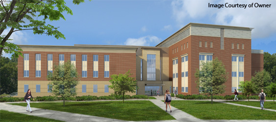
Figure 1: University Engineering Building Perspective Render - Courtesy of Owner
The interior space of the building is divided into different areas with specific functions. The rectangular east wing, roughly 22,000 SF is devoted to laboratory and research needs. The west wing, roughly 30,000 SF, is designated for classrooms, offices, computer labs, a learning center and graduate student areas. A state-of-the-art Clean Room is also included for research and lab needs. A remaining 15,000 SF is left unoccupied for future construction needs.
Major National Codes:
-State Fire Code - 2010
-International Building Code - 2009
-ASCE/SEI 7-05
NFPA 45, 101, 220, 5000 - 2009
Zoning: No zoning requirements needed for this project (University is exempt, verified by Municipality)
Historical Requirements: No historical requirements apply to this project
Building Enclosure
The same building enclosure patterns are used for both the West and East Wings. Levels 0-1 are wrapped with Limestone Block (Brick 2). Levels 2-Penthouse are wrapped with Red Brick (Brick 1). Curtain Wall window systems span the Brick 1 levels. The middle portion of the window is tinted to act as spandrel panels. The Connecting Wing features all Brick 2 with large curtain walls and an all glass entrance. The wall system is comprised of brick exterior, followed by an airspace, semi rigid insulation, spray applied vapor barrier, exterior sheathing and finally a metal stud and rigid insulation system on the interior face of the wall.
The main roofing system on the University Engineering Building is a fully adhered single ply TPO roofing system. Bolcing with metal coping is also present. The TPO membrane lies on 4" tapered rigid insulation, followed by a 1/2" layer of protection board, all on top of metal decking.
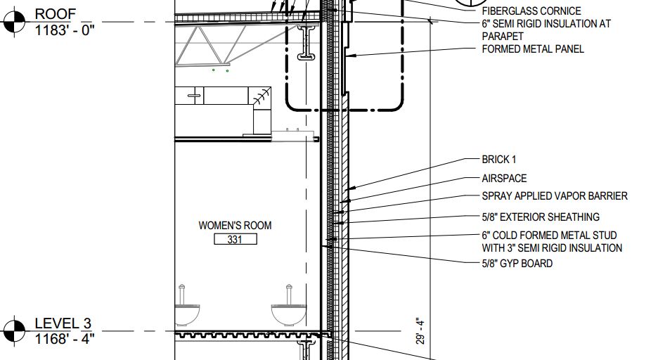
Figure 2: Wall Detail - Construction Docuements
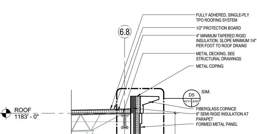
Figure 3: Roofing Detail - Construction Docuements
Sustainability Features
The LEED 2009 Checklist for New Construction and Major Renovations for this specific project is provided here.
|
Structural:
The UEB uses a concrete foundation system with a structural steel frame. The footing system is caissons, with each wing of the building utilizing caissons of different depths. A concrete retaining wall sets upon 2’ thick grade beams of varying widths, 2’ – 4’, and the wall itself is 24’ in height for the laboratory portion, while the office is only 10’. The laboratory building features slabs on grade at thicknesses of4” to 12” in specific areas based on loading. Slabs on deck are placed on 20 gage metal decking with slab thicknesses of 2.5” and 3”. All concrete, except the retaining wall (5000 psi), is 4000 psi strength. The framing system was sequenced for the laboratory and office as separate structures with a connecting structure. Typical wide flange members were used for both beams and columns and feature moment connections in specific areas. Steel erection will be completed using one 80-ton crawler crane that will maneuver around the building perimeter.
Mechanical:
The mechanical system for the University Engineering Building, is the most complex of all the building systems, due to the required need of extensive environmental controls. The UEB features two separate mechanical systems, one located at Level 0 and the Mezzanine, which sole purpose is to supply air to the clean room, level 0, mezzanine and part of the laboratory level 1. This system features 8 custom-built air-handling units equipped with fans and heat recovery units that can supply at the largest 44,000 CFM. To get a better grasp on the size of these units, they were installed during the steel erection phase because at no other point afterwards would they physically fit into the building.
The other mechanical system is located in the building penthouse on the laboratory wing of the building. This mechanical room supplies the remaining lab levels along with all three office levels. It features 6 custom-built air-handling units, smaller in size and output than the ones located in the Mezzanine. These units are elevated on reinforced concrete curbs to minimize the effect of vibrations on the UEB’s structural system and reduce noise. These units also have to be installed early than usual during the construction phase, when the slab on deck has been poured and cured but prior to the erection of the steel for the penthouse roof.
The laboratory spaces feature extensive exhaust systems centrally located to ease of construction and to collect all exhaust air from the three lab levels into one area. These shafts located in the labs house all necessary supply and return duct as well.
Electrical:
The UEB’s electrical system features two building service points, each including a 2500 kVA, 4160 V, 450 A transformer, furnished by the owner, and they both meet at the main building switchgear, 4000 A. From this point, power is supplied to two main distribution panels, 800 and 1200 A, then to panelboards ranging in sizes to feed power to the entire building. Temporary power is currently being supplied by the Soils and Foundations building located directly east of the UEB and will then supply its own power after construction is completed. Finally an emergency generator is located adjacent to the building to supply power to the labs in the case of an outage.
The University Engineering Building uses all fluorescent lighting with special lighting precautions used in the clean room and lab spaces.
Fire Protection:
The University Engineering Building utilizes a wet-pipe sprinkler system that covers 100% of the building area. Special exceptions have been made for fire suppression in particular areas, which include autoclave areas, electrical switchgear, transformer rooms, electrical closets, mechanical rooms and other areas in which high temperatures are experienced. Laboratory, mechanical room, electrical room, interstitial spaces, storage and the clean room area are all designated “Ordinary Hazard 2” sprinkler application schedule, while the remaining areas are designated light hazard.
Elevators:
The UEB features one elevator bay located in the laboratory wing of the building. Within this bay are housed two elevators, one for maintenance purposes and the other for building occupants.
Special Systems:
The key feature unique to the University Engineering Building is the clean room located in the basement level, Level 0. Design of the clean room was contracted out by the architect to Innovate Labs Systems Design, while construction of the space was contracted to Hodess Construction Corp. by the owner directly.
The clean room itself is free-standing and self-supported from the floor of the building, with lateral loads supported from the existing building by diagonal bracing with light gauge metal studs to the overhead structure. Air cleanliness classification and the definition of terms for clean room work are in accordance with ISO Class 1, 2, 3, 4, 5, 6 and 7.
Some design requirements for the clean room include; ambient room temperature must be held at 68°F ± 2°F, with relative humidity at 50% ±10%. Also, the overall leakage rate of the entire room and air handling system shall not exceed 3.5% of the total air supplied with the condition that all doors are closed and the room is in occupied condition. Lighting fixtures must be located so as to not conflict with equipment layout and the sound level within the clean room shall not exceed the (NC60) curve as determined by octave band analysis. |