REINSURANCE GROUP OF AMERICA (RGA) GLOBAL HEADQUARTERS |
|
16600 Swingley Ridge Road |
 |
Chesterfield, MO |
|
Natasha Beck |
|
Structural |
|
| Home |
|---|
| Student Bio |
| Building Statistics |
| Abstract |
| Technical Reports |
| Research |
| Proposal |
| Final Presentation |
| Final Report |
| Reflection |
| e-Studio Site |
General Building Data |
||
|---|---|---|
Building Name: |
Reinsurance Group of America (RGA) Global Headquarters | |
Location: |
16600 Swingley Ridge Road, Chesterfield, MO |
|
Occupant: |
Reinsurance Group of America, Inc. |
|
Occupancy Type: |
General office and training use for a Fortune 500 company |
|
Size: |
405,000 square feet |
|
Number of Stories: |
5 office levels above grade for each building (10 total), 2 parking levels below grade | |
Construction Dates: |
March 2013 to September 2014 | |
Cost Information: |
Estimated $150 million (More specific information is not available at this time) |
|
Delievery Method: |
Design-Build |
|
|
||
General Contractor: |
Clayco |
http://www.claycorp.com/ |
Architect: |
Gensler |
http://www.gensler.com/#home |
Structural Engineer: |
Uzun & Case |
http://www.uzuncase.com/index.htm |
Civil Engineer: |
Stock & Associates, Inc. |
http://www.stockassoc.com/home.htm |
Landscape Architect: |
Forum Studio |
http://www.forumstudio.com/ |
Lighting Consultant: |
Randy Burkett Lighting Design, Inc. |
http://www.rbldi.com/ |
MEP & Fire Protection Engineer: |
Environmental Systems Design, Inc. |
http://www.esdesign.com/ |
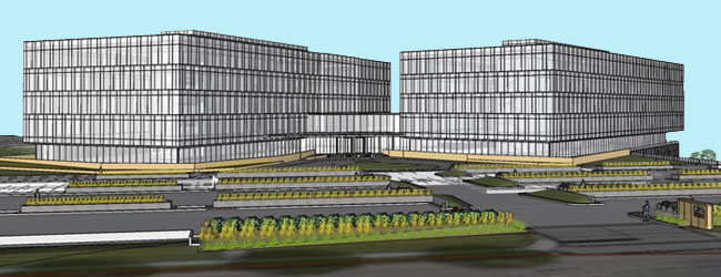
RGA Global Headquarters embodies flexibility and presence. Below grade is a two story concrete parking garage, exposed on the lower side of the site, giving rise to two identical, five story office buildings. An amenities level on the first floor of the complex connects the office buildings with the upper floors which are cantilevered over the amenities level. The "floor plates" of the office buildings exhibit an open floor plan that maximizes circulation and planning flexibility. Along the longitudinal axes of the offices is a series of service cores for mechanical systems, restrooms, elevators and stairs.
| Applicable Codes | |
|---|---|
Building: |
International Building Code, IBC 2009 amended by Ordinance 24, 444-2010 |
State/County: |
St. Louis County Ordinances |
Structural: |
American Society of Civil Engineers, ASCE 7-05 |
| American Concrete Institute, ACI 318-08 | |
American Institute of Steel Construction, AISC 360-05 |
|
Masonry: ACI 530/ASCE 5/TMS 402 |
|
Mechanical: |
International Mechanical Code, IMC 2009 |
Electrical: |
National Electrical Code, NEC 2008 |
Plumbing: |
Uniform Plumbing Code, UPC 2009 |
Energy: |
International Energy Conservation Code, IECC 2009 |
Zoning
C-8: Planned Commercial District
Building height, lot coverage, and setbacks to be approved by building official
Not Applicable
Historical Requirements
Not Applicable
Building Envelope
Because the owner showed interest in several types of building materials, the façade has two main elements. A curtain wall system comprised of reflective silver, ceramic fritted, and gray finished glasses encase the offices. With sustainability in mind, the glass units consist of two low iron, low E panes with an argon filled air space. Where the parking deck is exposed on the lower side, or state highway side, of the site, the façade is limestone panels, thermally broken where possible, with honed or bush hammered finishes make up the façade.
The roofing system consists of a single ply Thermoplastic Polyolefin Sheet (TPO) membrane that complies with the LEED Solar Reflectance Index requirement. Additional insulation in the form of a cementitious fill material and Expanded Polystyrene (EPS) is provided. This roofing system is supported on composite acoustical deck system.
Sustainability Features
Three bio-retention basins are showcased on the state highway side of the site. These basins utilize a combination of vegetation, engineered soils and sloping landscape to treat water runoff through biological and chemical processes, resulting in clean water. This water then either disperses into the surrounding natural soils or is directed into the storm water draining system.
RGA Global Headquarters has a project goal and design basis of achieving LEED Silver Certification.
Superstructure:
The two office tower structures are constructed A992 grade 50 steel. The floors are 3 inch composite metal deck with 3 1/2 inch semi-lightweight concrete topping of 3000 psi. Typical gravity beams are W14x22, W16x26, W18x35, W21x44, W21x50, and W24x62 with cambers of 3/4 inch to 1 3/4 inch. Roof construction is 3 inch 20 gage type N roof deck with roof beams of W21x57, W21x44, W12x19, and W8x18 with cambers 3/4". Gravity columns on lower levels are larger, typically W10x49, W12x65, W12x79, W12x87, W12x136 while smaller on upper levels, typically W12x65, W12x58, W12x53 with the column splices occurring 4 ft. above Level 04. The 40 ft., four floor cantilever is supported by a truss system with the compression columns bearing on a 4 ft. deep plate girder spanning between them. On the roof level where the top of the tension members meet the roof beams the beams are designed to take axial tension, which decreases further away from the cantilever. (More details are available in Technical Report 1).
Substructure:
A two story, reinforced concrete parking garage of post-tensioned one-way slabs and post-tensioned beams make up the substructure. Since the site slopes from one side to the other, parts of the garage are exposed and are finished with 3 inch thick limestone façade panels. In terms of soil load, perimeter beams are designed to take the entire soil load, but any surcharge load is handled by a tie-back system that was designed by a specialty firm. Slab thicknesses range from 5 inches to 9 1/2 inches depending on the type of loading it is expected to see. Besides post-tensioned beams, there is a 25 inch deep pan joist system to support a landscaped terrace on Level 01. This system has a 5 inch slab thickness with joists spaced at a maximum of 6 ft. Columns in the parking garage are typically 5000 psi concrete and range in size from 16"x16" up through 32"x32" with the most common size being 24"x24" for square and rectangular columns. Circular columns range in diameters of 24 inches to 36 inches with the most common diameter being 28 inches.
Foundation:
Predominant soils in the area include topsoil, clays, areas of shale, an area of unknown fill, and bedrock with groundwater appearing anywhere from 37' ft. to 60 ft. below existing grade. This and the relative proximity to a fault line led to a Site Class C designation. The foundation consists first of drilled piers on roughly a 30 ft. by 40 ft. grid and an allowable end bearing pressure of 80 ksf. These piers are 3000 psi concrete and have vertical reinforcement of #8 through #11 bars and have diameters of 36 inches to 78 inches. Where competent bedrock is near the surface, which is localized to the Northeast corner of the complex, rock and soil bearing spread footings are used. Finally, the grade beams spanning between piers range in size from 18"x18" to 42"x24" and are 4000 psi concrete.
Lateral System:
In the superstructure, the lateral system is steel chevron braced frames. Typical column sizes for the brace frames are W12x152, W12x136 and W12x120 for the first three stories decreasing to W12x87 for stories four and five. Beam sizes include W24x84, W24x76, W24x68, W24x55, W21x68, W18x46, W18x35, W14x22 and W16x26. The bracing members are HSS 6x6 to HSS 10x10 with thicknesses of ½” or 5/8”. In the substructure, 16 inch thick reinforced 5000 psi concrete shear walls sit below the steel braced frames. At Level 01, the steel braced frames in each office tower are pin connected to the top of the concrete shear walls so that they act together as one system to resist the lateral load. A structural isolation joint separates the parking structure under the office towers from the rest of the garage to mitigate the seismic mass of the garage.
RGA Global Headquarters is a $150 million design-build project. The complex is approximately 405,000 gross square feet and has a finish elevation above grade of 85 ft. There are no strict height limits, existing utilities, or previous construction associated with the existing site. Five of its stories are completely above ground and two stories are built into a hill. Construction on the project began in March 2013 and will continue until September 2014.
The mechanical equipment and lighting fixtures run on 480/277 volt system while the office receptacles step down to a 208/120 volt system. Electricity is fed by 3-phase, 4 wire buses into four main switch boards which are rated for 3000 amperes. The Core and Shell design supplied panelboards rated for 100, 225, 400, 600 and 800 amperes. Finally, emergency and standby equipment in the complex is supported by diesel engine generators.
Tennant fit out design for interior electrical is currently in progress and information will be posted as it becomes available.
Most exterior and all emergency lighting is LED lamps and assorted fixtures. Walkway lighting is utilizes recessed and handrail fixtures while the parking lot fixture is a gantry light pole. Uplighting is accomplished with fluorescent lamps having both electronic and magnetic ballasts. Exterior lighting and interior restroom lighting run on a 277 volt system.
Tennant fit out design for interior lighting is currently in progress and information will be posted as it becomes available.
Core and Shell:
The mechanical system for the complex is designed for year-round cooling. This cooling is supplied by three cross flow cooling towers which service three, 650 ton water cooled chiller units. Two 60,000 CFM air handling units service each office tower and four others of various sizes serve various segments of the amenities spaces. Office tower AHU’s are located in a mechanical penthouse on the roof of each tower. Air is supplied to each floor of the offices by a medium pressure loop with VAV branch capability as needed for the interior fit out. Additionally, three fan powered terminal units in each office tower provide heat to the floor cavity of the outlook cantilever to counteract the space’s potential for a heat sink. Finally, all of these components are integrated into the complex's Building Automation System (BAS).
Interior:
Tennant fit out design for interior mechanical is currently in progress and information will be posted as it becomes available.
The design follows the fire protection requirements set by the International Building Code (IBC) and by the National Fire Protection Association (NFPA). The complex is fully sprinkled with a wet pipe sprinkler system and has smoke and heat detectors both in the public spaces and the HVAC ducts. The BAS is also encoded with the necessary fire protection protocols. The fire protection system itself is a Remote Station Protective Signaling System meaning that when an alarm is triggered it is transmitted to a remote location usually over a telephone wire to alert fire authorities. This type of system is typical for private offices and buildings that spend extended periods unoccupied. Fire ratings needed in the design were one hour roof construction and two hour floor construction, structural members, and stair and elevator shafts. Between the lower amenities levels and the parking garage required a three hour fire separation for all walls and doors.
Tennant fit out design for interior telecommunications is currently in progress and information will be posted as it becomes available.
Tennant fit out design for interior telecommunications is currently in progress and information will be posted as it becomes available.